Stroboscopic device

a stroboscopic device and stroboscopic technology, applied in the field of stroboscopic devices, can solve the problems of spark (discharge) and the disadvantage is particularly noticeable, and achieve the effects of preventing or suppressing the occurrence of sparks, high reliability, and long service li

Active Publication Date: 2014-01-02
PANASONIC INTELLECTUAL PROPERTY MANAGEMENT CO LTD
View PDF0 Cites 5 Cited by
  • Summary
  • Abstract
  • Description
  • Claims
  • Application Information

AI Technical Summary

Benefits of technology

[0015]This avoids the situation of less light emission of the flash discharge tube or stoppage of light emission. As a result, occurrence of sparks can be prevented or suppressed, achieving the flash discharge tube with long service life and high reliability.

Problems solved by technology

This is likely to cause spark (discharge).
The above disadvantage is particularly noticeable in case of light emissions for communications by communications signals using consecutive light-emitting pattern between master strobe and slave strobe, or continuous light emission such as flat light emission that keeps long light-emitting time by intermittent light emission at fine pitch (e.g., 50 kHz).

Method used


Image

  • Stroboscopic device
  • Stroboscopic device
  • Stroboscopic device

Examples


Embodiment Construction

[0022]An exemplary embodiment of a stroboscopic device of the present invention is described below with reference to drawings. In the following description, same reference marks are given to same or equivalent components.

EXEMPLARY EMBODIMENT

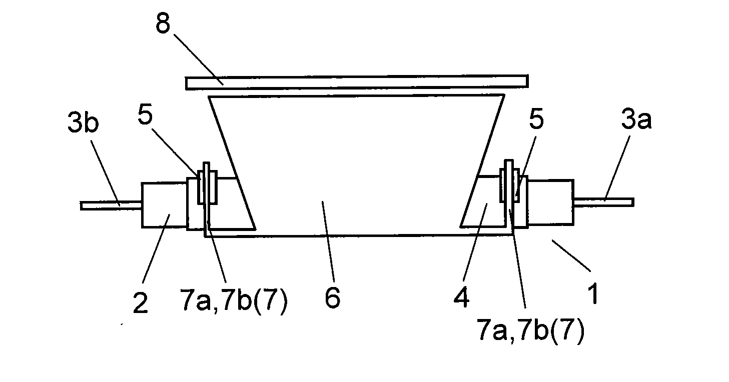
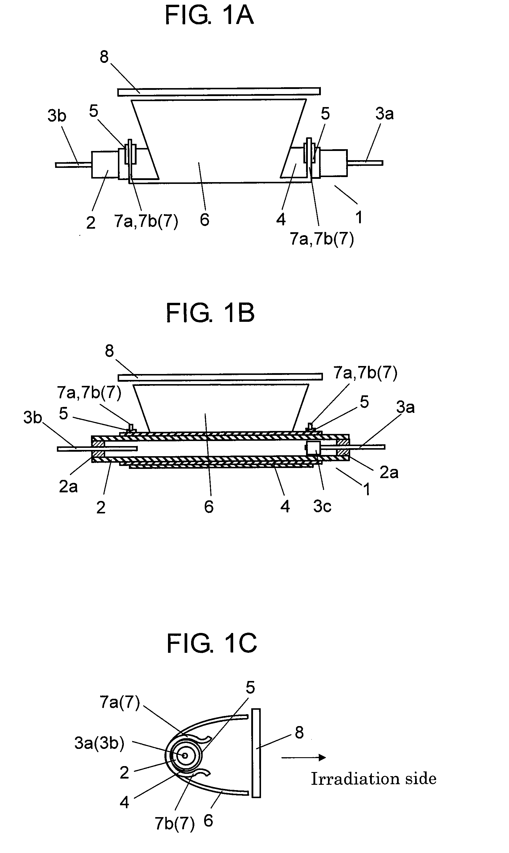
[0023]The stroboscopic device in the exemplary embodiment of the present invention is described below with reference to FIGS. 1A to 1C. FIG. 1A is a front view of the stroboscopic device in the exemplary embodiment of the present invention. FIG. 1B is a front sectional view of the stroboscopic device in the exemplary embodiment. FIG. 1C is a side view of the stroboscopic device in the exemplary embodiment.

[0024]As shown in FIGS. 1A to 1C, the stroboscopic device in the exemplary embodiment at least includes straight flash discharge tube 1, conductive film 4 formed on an outer periphery of flash discharge tube 1, conductive medium 5 laminated on a part of conductive film 4, reflector 6 into which flash discharge tube 1 is inserted, and optical pan...


PUM


Abstract

A stroboscopic device includes a flash discharge tube with a conductive film on its outer periphery, a conductive reflector into which the flash discharge tube is inserted, and a heat-resistant conductive medium laminated on a part of the conductive film of the flash discharge tube. The reflector is electrically connected to the conductive film of the flash discharge tube via the conductive medium. This achieves the stroboscopic device with long service life and high reliability by preventing or suppressing occurrence of spark.

Description

[0001]This application is a U.S. National Phase Application of PCT International Application PCT / JP2012 / 002018.TECHNICAL FIELD[0002]The present invention relates to stroboscopic devices used as artificial light source for photography using cameras (imaging devices) equipped with photosensitizing agent, such as silver halide film, or image pickup device, such as CCD image sensor and CMOS image sensor.BACKGROUND ART[0003]Conventionally, this type of stroboscopic device is configured as shown in FIGS. 3A and 3B. FIG. 3A is a front view of a conventional stroboscopic device, and FIG. 3B is a side view of the conventional stroboscopic device.[0004]As shown in FIGS. 3A and 3B, the conventional stroboscopic device includes flash discharge tube 1 having glass bulb 2 in which xenon (Xe) is filled and at least a pair of electrodes 3a and 3b sealed at its both ends, reflector 6 into which flash discharge tube 1 is inserted, and optical panel 8 disposed at the front of reflector 6. The conventi...

Claims


Application Information

Patent Timeline
Patent Type & Authority Applications(United States)
IPC IPC(8): H01J61/80F21Y101/00
CPCH01J61/80G03B15/05G03B2215/0578G03B2215/0582
Inventor TSUCHIDA, SHIGERU
Owner PANASONIC INTELLECTUAL PROPERTY MANAGEMENT CO LTD
Why Eureka
Try Eureka