Magnetic element for wireless power transmission and method for manufacturing same

Inactive Publication Date: 2014-01-02
NITTO DENKO CORP
View PDF4 Cites 31 Cited by
  • Summary
  • Abstract
  • Description
  • Claims
  • Application Information

AI Technical Summary

Benefits of technology

[0033]There is provided a magnetic element for wireless power transmission, which has a high heat dissipation performance a

Problems solved by technology

However, feeding high power with high power transmission efficiency in such a magnetic element for wireless power transmission causes an excessive heat generation.
Thi

Method used


Image

  • Magnetic element for wireless power transmission and method for manufacturing same
  • Magnetic element for wireless power transmission and method for manufacturing same
  • Magnetic element for wireless power transmission and method for manufacturing same

Examples


example 1

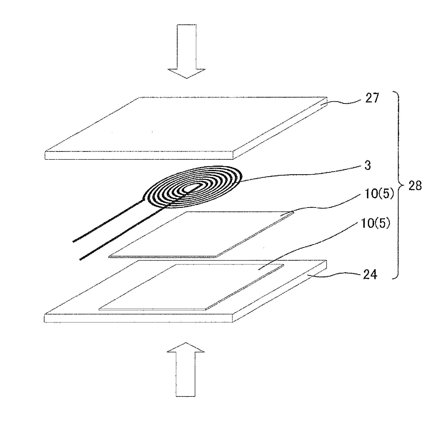
[0099]The above described magnetic elements 1 and 2 were used in Example 1. As shown in FIG. 6, the magnetic element 1 on the power feeding end and the magnetic element 2 on the power receiving end were disposed to face each other. At this time, the magnetic element 1 and the magnetic element 2 were spaced from each other by a distance of 3 mm. The elements were further disposed so that the shaft center of the planar coil 3 and that of the planar coil 4 coincided with each other. After this, a wire bonded with the one end portion on the outer circumference side and a wire bonded with the other end portion on the inner circumference side of the planar coil 3 were connected to terminals 41 of a network analyzer 40 (Agilent Technologies, Inc.) Further, a wire bonded with the one end portion on the outer circumference side and a wire bonded with the other end portion on the inner circumference side of the planar coil 4 were connected to a terminal 42 of the network analyzer 40 (Agilent ...

example 3

Measurement Results of Example 3, Comparative Example 2, Comparative Example 3, Comparative Example 4

[0111]The results of the above measurements are shown in FIG. 9 and FIG. 10, FIG. 9A shows the surface temperature of the magnetic element 1 related to Example 3. FIG. 9B shows the surface temperature of the planar coil 3 related to Comparative Example 2. FIG. 10C shows the surface temperature of the planar coil 59 related to Comparative Example 3. FIG. 10D shows the surface temperature of the magnetic element 58 related to Comparative Example 3.

[0112]In the above measurements, the resulting surface temperatures of the outer edge portion T1, the pcenter ortion T2, the midway portion T3 of the magnetic element 1 related to Example 3 were 45.2° C., 52.2° C., and 54.7° C., respectively. Further, the resulting surface temperatures of the outer edge portion T1, the pcenter ortion T2, and the midway portion T3 of the planar coil 3 related to Comparative Example 2 were 41.6° C., 58.8° C., ...


PUM

PropertyMeasurementUnit
Pressureaaaaaaaaaa
Electric potential / voltageaaaaaaaaaa
Efficiencyaaaaaaaaaa

Abstract

The purpose of the present invention is to provide: a magnetic element for wireless power transmission, which is capable of feeding power with high power transmission efficiency, while increasing the heat dissipation performance; and a method for manufacturing the magnetic element for wireless power transmission magnetic element for wireless power transmission have configurations that respectively comprise planar coils through which an alternating current passes and magnetic parts which are arranged in parallel in the intervals between the copper wires of the planar coils when viewed in cross section. The magnetic parts comprise an epoxy resin in which iron-based amorphous particles FINEMET® serving as magnetic particles are dispersed, and the magnetic parts are integrated with the planar coils by being bonded to the planar coils in an electrically insulated state by means of the epoxy resin.

Description

TECHNICAL FIELD[0001]The present invention relates to magnetic elements for wireless power transmission, which enables contactless power transmission.BACKGROUND ART[0002]There have been an increasing number of machines activated by cordless power supply utilizing electromagnetic inductance, such as electric toothbrushes, cordless telephones, and portable devices (e.g., PTL 1). There have also been developments of machines activated by cordless power supply utilizing magnetic resonance, in relation to wall-hang television sets and personal computers (e.g., PTL 2). To add this, there have been many developments and suggestions for magnetic elements for wireless power transmission capable of feeding high power with high power transmission efficiency, in the field of wireless power transmission.[0003]However, feeding high power with high power transmission efficiency in such a magnetic element for wireless power transmission causes an excessive heat generation. This generated heat in th...

Claims


Application Information

Patent Timeline
IPC IPC(8): H01F38/14H01F41/02H01F17/00H01F17/04H01F41/04
CPCH01F38/14H01F41/02H01F1/15375H01F17/043H01F27/2823H01F41/0246Y10T29/4902
Inventor HATANAKA, TAKEZOGOTO, CHISATO
Owner NITTO DENKO CORP
Why Eureka
Try Eureka