

Image pickup lens
a pickup lens and image technology, applied in the field of image pickup lenses, can solve the problems of not being able to say, the lens provides a sufficiently bright lens system or a wide angle, and the image pickup lens is described, and achieves the effects of small f-value, reduced size and thinning, and high resolution
- Summary
- Abstract
- Description
- Claims
- Application Information
AI Technical Summary
Benefits of technology
Problems solved by technology
Method used
Image

Examples
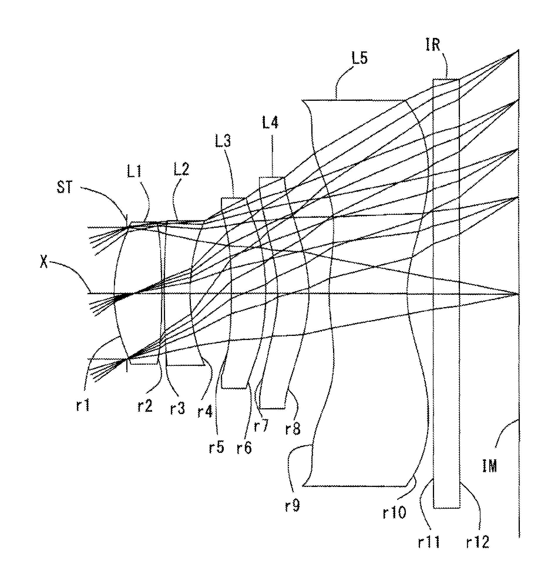
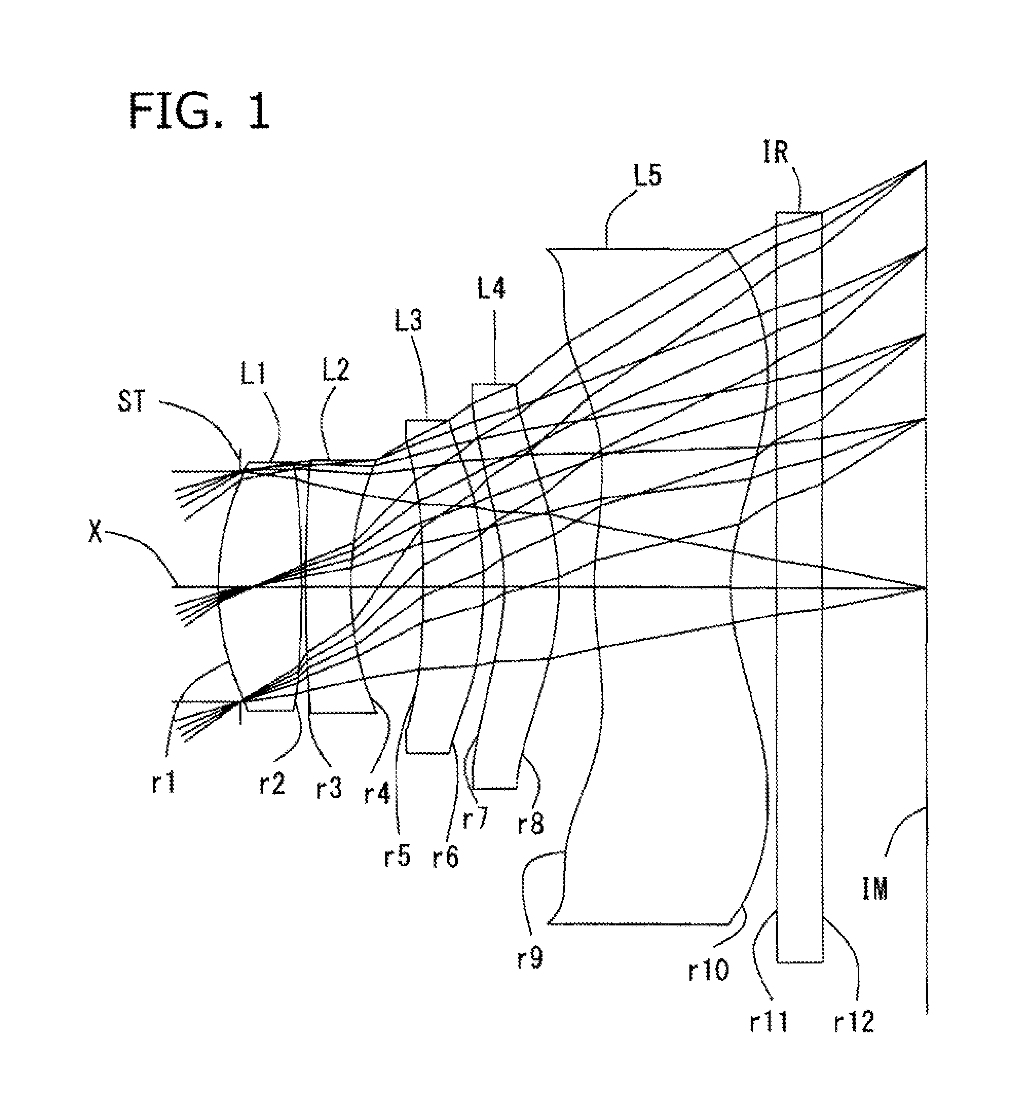
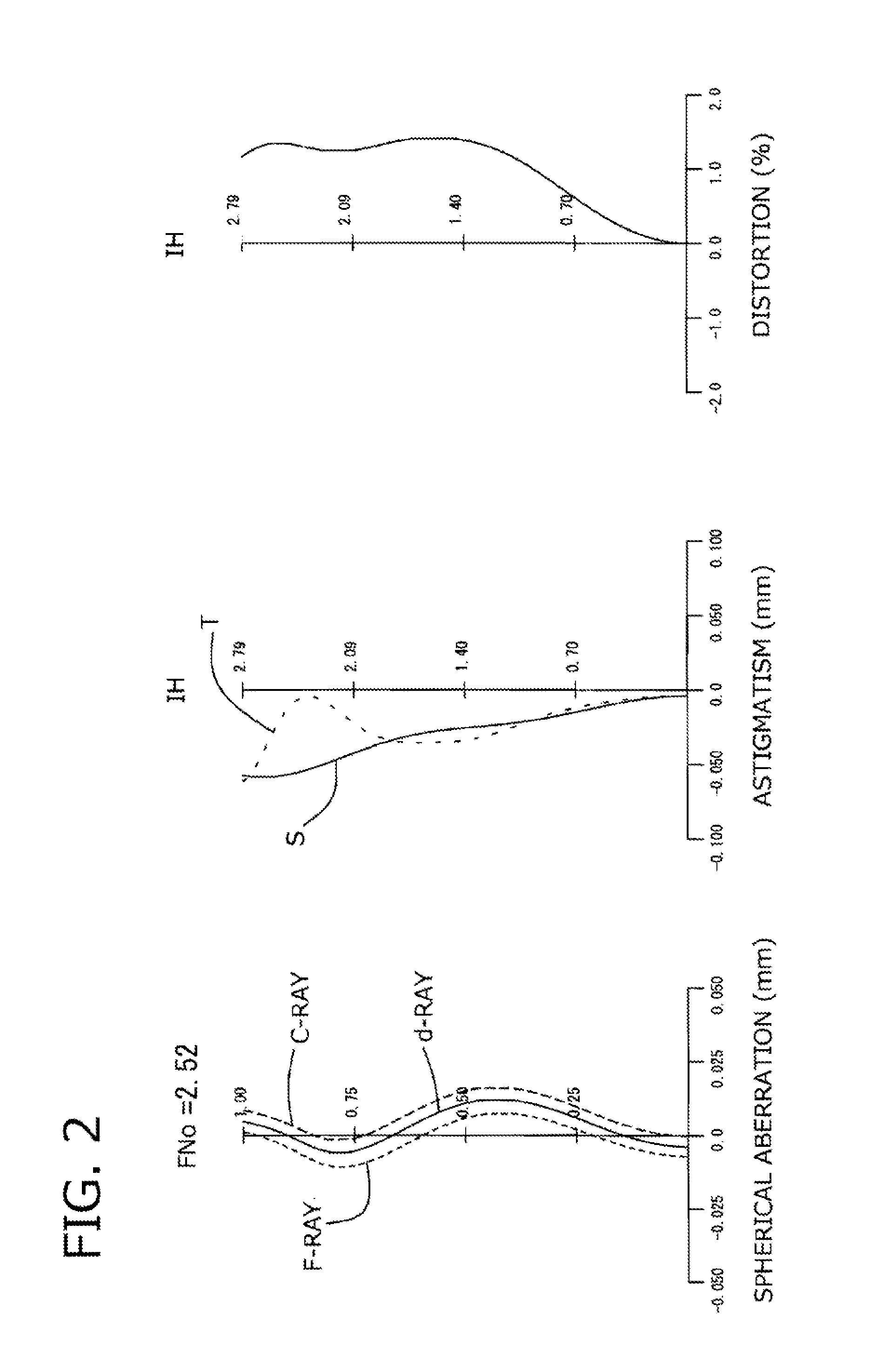
embodiment 1
[0057]Basic lens data are shown in Table 1 below.
TABLE 1Embodiment 1Unit mmf = 3.810Fno = 2.52ω(°) = 35.78IH = 2.791Surface DataRefractive IndexAbbe NumberSurface No. iCurvature Radius rSurface Distance dNdνd(Object Surface)InfinityInfinity 1 (Stop)Infinity−0.145 2*1.6540.5491.535156.12 3*−6.6190.025 4*12.4240.3001.635523.91 5*2.2110.474 6*−10.4400.4161.535156.12 7*−3.1310.137 8*−1.4320.3541.535156.12 9*−1.5880.23710*2.3240.8971.535156.1211*1.3860.30012Infinity0.31.516864.2013Infinity0.680Image PlaneInfinityAspherical Surface Data2nd Surface3rd Surface4th Surface5th Surface6th Surfacek−1.802E+001.351E+010.000E+001.732E+002.721E+00A42.749E−028.503E−023.580E−02−5.643E−02−1.233E−01A61.542E−02−2.531E−01−3.023E−022.019E−01−2.662E−02A8−4.323E−022.421E−01−1.422E−01−3.714E−011.753E−01A10−3.872E−02−1.266E−013.071E−013.347E−01−6.943E−02A12−8.698E−036.959E−03−1.103E−01−7.921E−02−3.900E−02A140.000E+000.000E+000.000E+000.000E+00−1.200E−04A160.000E+000.000E+000.000E+000.000E+000.000E+007th Surfac...
embodiment 2
[0061]Basic lens data are shown in Table 2 below.
TABLE 2Embodiment 2Unit mmf = 3.805Fno = 2.38ω(°) = 35.98IH = 2.791Surface DataRefractive IndexAbbe NumberSurface No. iCurvature Radius rSurface Distance dNdνd(Object Surface)InfinityInfinity 1 (Stop)Infinity−0.145 2*1.5580.5561.534656.16 3*−5.3690.025 4*25.7310.3001.614225.58 5*2.1760.497 6*−9.4660.4211.534656.16 7*−3.5510.138 8*−1.4100.3461.534656.16 9*−1.5620.22710*2.3530.8701.534656.1611*1.4090.30012Infinity0.3001.516864.2013Infinity0.617Image PlaneInfinityAspherical Surface Data2nd Surface3rd Surface4th Surface5th Surface6th Surfacek−1.722E+001.350E+010.000E+001.798E+003.100E+01A42.965E−028.554E−023.886E−02−5.670E−02−1.286E−01A61.582E−02−2.568E−01−2.433E−022.089E−01−3.491E−02A8−5.394E−022.280E−01−1.416E−01−3.519E−011.679E−01A10−6.862E−02−1.582E−012.921E−013.496E−01−7.333E−02A12−2.789E−02−4.843E−02−1.547E−01−1.287E−01−3.876E−02A140.000E+000.000E+000.000E+000.000E+006.334E−03A160.000E+000.000E+000.000E+000.000E+000.000E+007th Surfa...
embodiment 3
[0065]Basic lens data are shown in Table 3 below.
TABLE 3Embodiment 3Unit mmf = 3.894Fno = 2.58ω(°) = 35.30IH = 2.791Surface DataRefractive IndexAbbe NumberSurface No. iCurvature Radius rSurface Distance dNdνd(Object Surface)InfinityInfinity 1 (Stop)Infinity−0.145 2*1.6440.5591.544115.98 3*−4.4080.025 4*−12.9950.3001.583730.13 5*2.0920.476 6*−100.0000.4221.544155.98 7*−3.3120.157 8*−1.3830.3241.544156.98 9*−1.5550.23410*2.2860.8721.544155.9811*1.4050.30012Infinity0.31.516864.2013Infinity0.796Image PlaneInfinityAspherical Surface Data2nd Surface3rd Surface4th Surface5th Surface6th Surfacek−1.829E+001.841E+010.000E+002.083E+000.000E+00A42.742E−029.983E−023.710E−02−5.179E−02−1.049E−01A61.508E−02−2.726E−01−2.474E−022.326E−01−2.892E−02A8−6.244E−022.116E−01−1.994E−01−3.869E−011.664E−01A10−7.095E−02−1.273E−011.627E−012.928E−01−7.478E−02A12−3.371E−02−8.438E−02−2.463E−02−1.143E−01−3.460E−02A140.000E+000.000E+000.000E+000.000E+001.437E−02A160.000E+000.000E+000.000E+000.000E+000.000E+007th Surf...
PUM
 Abstract
Description
Claims
Application Information