Organic light emitting display
a light-emitting display and organic technology, applied in the direction of spectral modifiers, lighting and heating apparatuses, lighting device details, etc., can solve the problems of deteriorating aperture ratio, achieve high aperture ratio, increase the area, and secure the degree of design freedom
- Summary
- Abstract
- Description
- Claims
- Application Information
AI Technical Summary
Benefits of technology
Problems solved by technology
Method used
Image
Examples
first embodiment
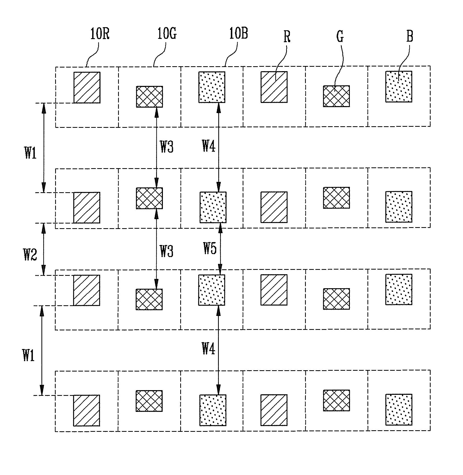
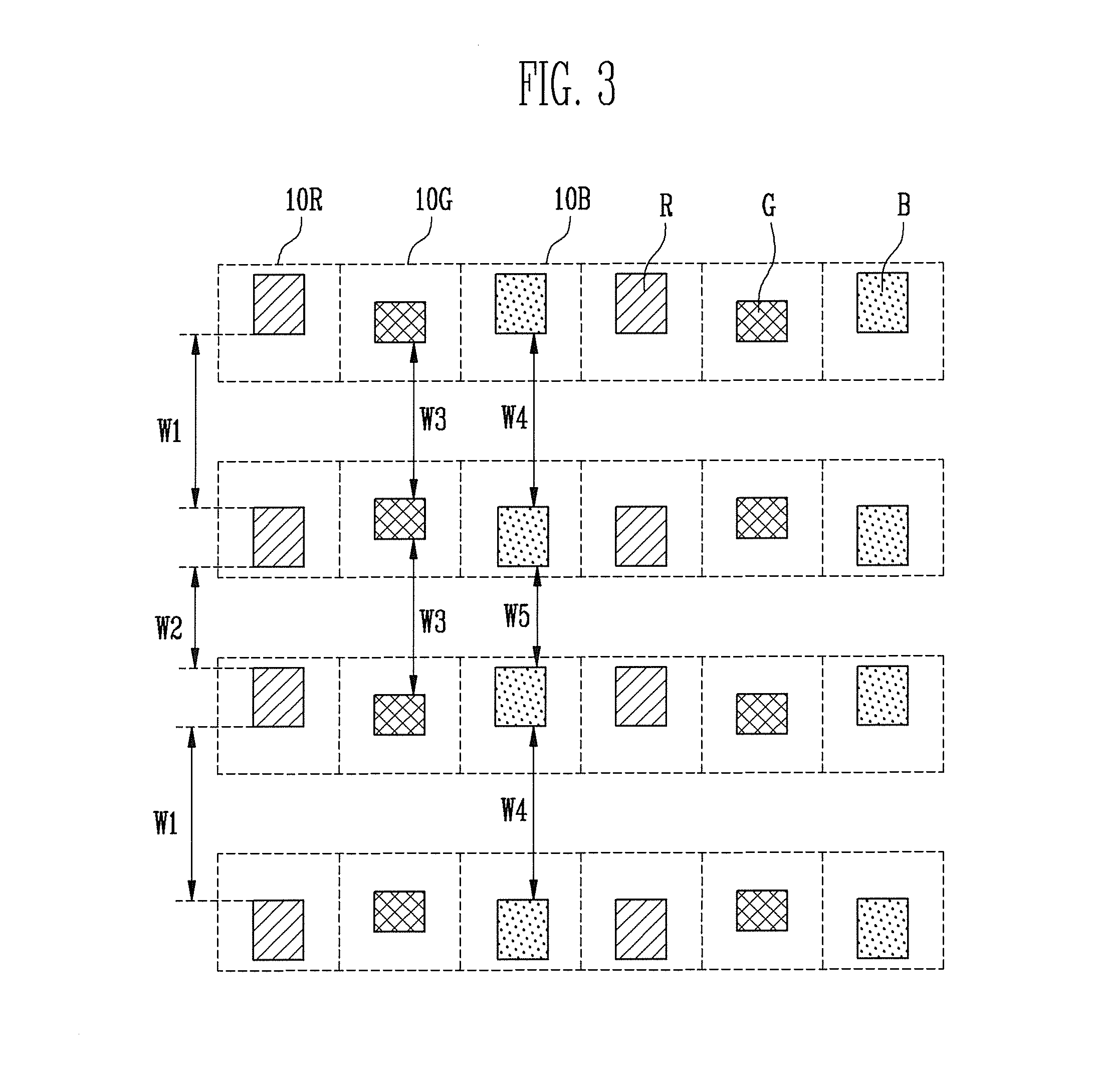
[0033]FIG. 3 is a view illustrating a pixel structure of an organic light emitting display according to the present invention.
[0034]Referring to FIG. 3, the organic light emitting display according to the first embodiment of the present invention includes red pixels 10R, green pixels 10G, and blue pixels 10B. The red pixels 10R, the green pixels 10G, and the blue pixels 10B are repeatedly arranged in horizontal lines, and the pixels 10R, 10G, and 10B that emit light components of the same color are repeatedly arranged in vertical lines. That is, the organic light emitting display of FIG. 3 has a structure in the form of stripes.
[0035]The red pixels 10R include red emission regions R for generating red light. The green pixels 10G include green emission regions G for generating green light.
[0036]The blue pixels 10B include blue emission regions B for generating blue light. Here, the green emission regions G are arranged at substantially uniform intervals, and the blue emission regions...
second embodiment
[0042]FIG. 4 is a view illustrating a pixel structure of an organic light emitting display according to the present invention.
[0043]Referring to FIG. 4, the organic light emitting display according to the second embodiment includes red pixels 20R, green pixels 20G, and blue pixels 20B. The organic light emitting display of FIG. 4 according to the present invention has a structure in the form of stripes.
[0044]The red pixels 20R include red emission regions R for generating red light. The green pixels 20G include green emission regions G for generating green light. The blue pixels 20B include blue emission regions B for generating blue light.
[0045]Here, a specific red emission region R is separated from an adjacent red emission region R above the red emission region R, and is separated from another adjacent red emission region R below the red emission region R at the tenth distance W10. A specific green emission region G is separated from an adjacent green emission region G above the ...
third embodiment
[0048]FIG. 5 is a view illustrating a pixel structure of an organic light emitting display according to the present invention.
[0049]Referring to FIG. 5, the organic light emitting display according to the third embodiment of the present invention has a delta structure (e.g., a hexagon structure) in which pixels 30R, 30G, and 30B of one unit pixel are positioned in two horizontal lines.
[0050]The red pixels 30R include red emission regions R for generating red light. The green pixels 30G include green emission regions G for generating green light. The blue pixels 30B include blue emission regions B for generating blue light. Here, the green emission regions G are arranged at uniform intervals, and the blue emission regions B are arranged at different intervals. The red emission regions R are arranged at different intervals.
[0051]In more detail, the distance between a red emission region R and an adjacent red emission region R above the red emission region R is different from the dista...
PUM
 Abstract
Description
Claims
Application Information
 - R&D
- Intellectual Property
- Life Sciences
- Materials
- Tech Scout
- Unparalleled Data Quality
- Higher Quality Content
- 60% Fewer Hallucinations
Browse by: Latest US Patents, China's latest patents, Technical Efficacy Thesaurus, Application Domain, Technology Topic, Popular Technical Reports.
© 2025 PatSnap. All rights reserved.Legal|Privacy policy|Modern Slavery Act Transparency Statement|Sitemap|About US| Contact US: help@patsnap.com


