Multi-facet light engine

a light engine and facet technology, applied in the field of multi-facet light engines, can solve the problems of reducing efficiency, adding additional optical elements, adding cost and complexity to the lighting assembly,

Inactive Publication Date: 2014-01-02
FLEXTRONICS AP LLC
View PDF6 Cites 13 Cited by
  • Summary
  • Abstract
  • Description
  • Claims
  • Application Information

AI Technical Summary

Benefits of technology

[0008]In some embodiments, the first planar surface is parallel to the external illumination surface. In some embodiments, the first planar surface and the plurality of second planar surfaces are angled to provide a determined lighting pattern on the external illumination surface. In some embodiments, each second substrate is rotatably coupled to the first substrate so as to enable change of the angle at which the second substrate is coupled to the first substrate. In some embodiments, the angle that each second substrate is positioned relative to the first substrate is the same. In other embodiments, the angle that one or more of the second substrates is positioned relative to the first substrate is different. In some embodiments, the first substrate includes a plurality of first outer edges and each second substrate includes at least a second outer edge, further wherein the second outer edge of each second substrate is coupled to a corresponding one first outer edge of the first substrate. In some embodiments, a number of first outer edges equals a number of second substrates. In other embodiments, a number of first outer edges is not equal to a number of second substrates.

Problems solved by technology

Although useful to reduce shadowing effects, the additional optical elements reduce efficiency and add cost and complexity to the lighting assembly.

Method used


Image

  • Multi-facet light engine
  • Multi-facet light engine
  • Multi-facet light engine

Examples


Embodiment Construction

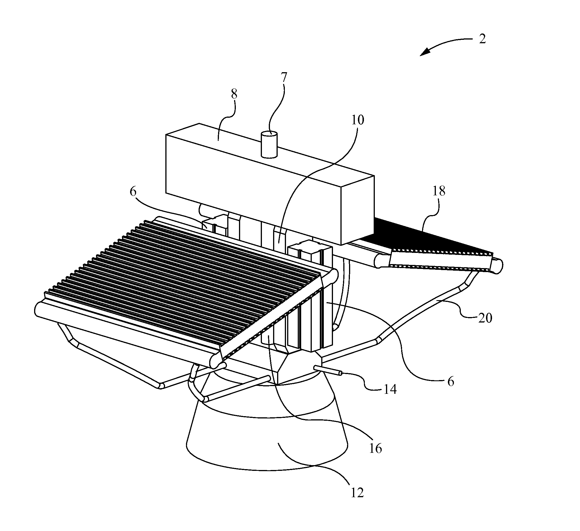
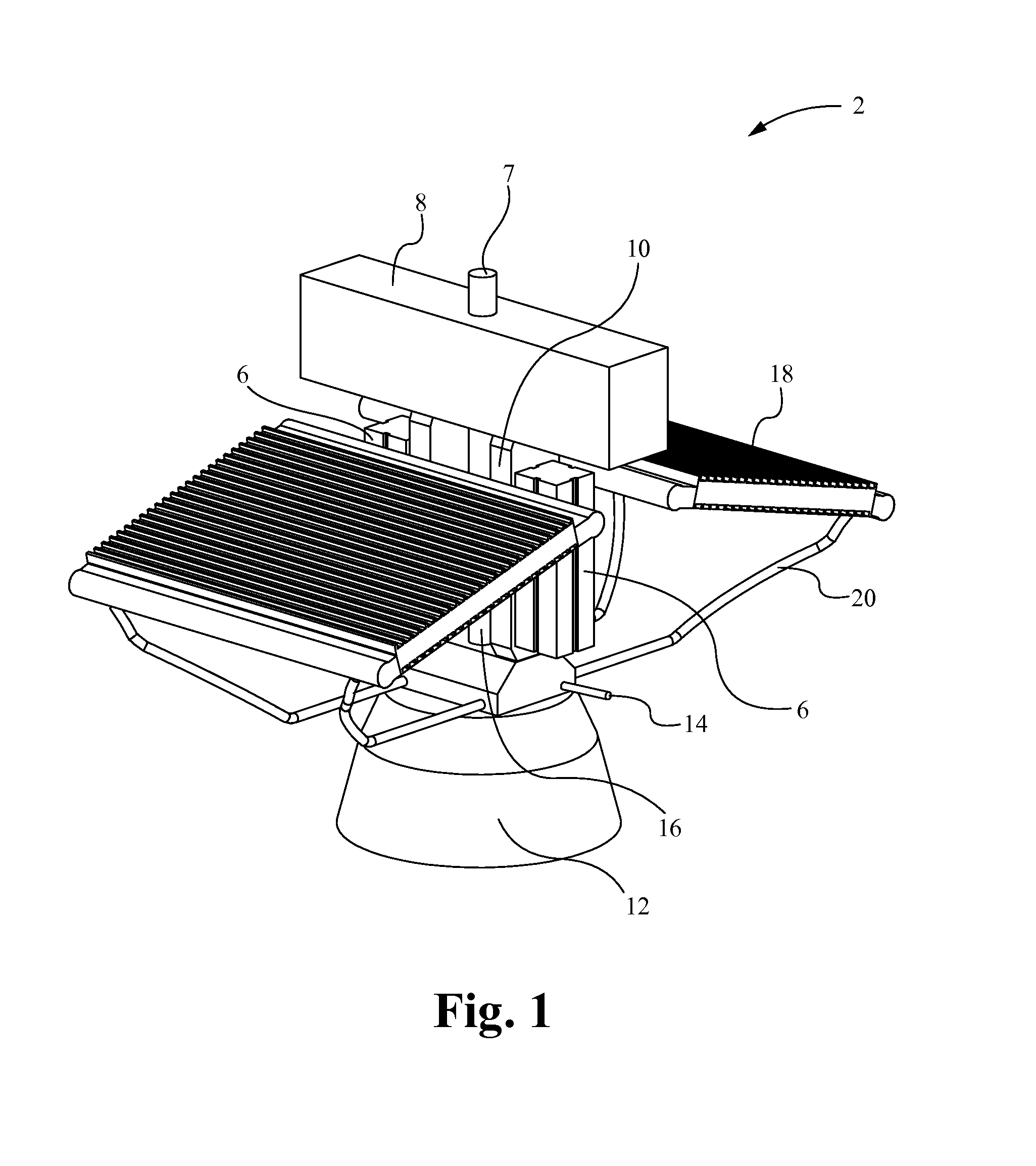
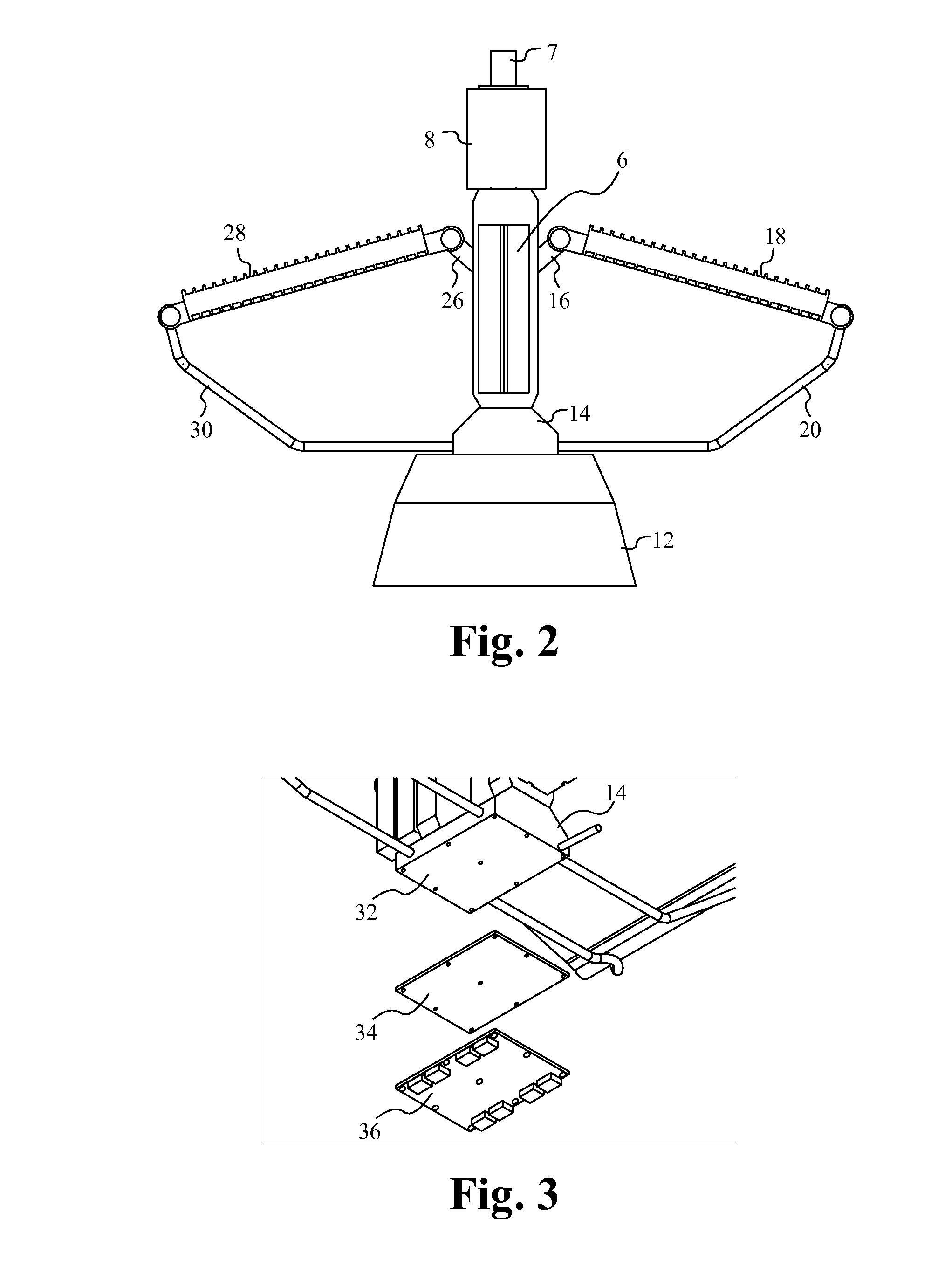
[0021]Embodiments of the present application are directed to a lighting assembly. Those of ordinary skill in the art will realize that the following detailed description of the lighting assembly is illustrative only and is not intended to be in any way limiting. Other embodiments of the lighting assembly will readily suggest themselves to such skilled persons having the benefit of this disclosure.

[0022]Reference will now be made in detail to implementations of the lighting assembly as illustrated in the accompanying drawings. The same reference indicators will be used throughout the drawings and the following detailed description to refer to the same or like parts. In the interest of clarity, not all of the routine features of the implementations described herein are shown and described. It will, of course, be appreciated that in the development of any such actual implementation, numerous implementation-specific decisions must be made in order to achieve the developer's specific goa...


PUM


Abstract

A lighting assembly includes a plurality of LEDs configured as a multi-facet light engine. A first group of LEDs are arrayed as a main light source and the remaining LEDs are angled relative to the first group of LEDs to generate an intended lighting pattern. The first group of LEDs are arrayed on a first planar surface of a first substrate, and the remaining LEDs are arrayed on second planar surfaces of additional substrates positioned around the first substrate. The planar surfaces of the additional substrates are angled relative to the planar surface of the first substrate. The angles of the second planar surfaces to the first planar surface can be application specific and can be acute or obtuse.

Description

RELATED APPLICATIONS[0001]This Patent Application claims priority under 35 U.S.C. 119 (e) of the co-pending U.S. provisional application, Ser. No. 61 / 665,179, filed Jun. 27, 2012, and entitled “LED LIGHTING” and U.S. provisional application, Ser. No. 61 / 673,660, filed Jul. 19, 2012, and entitled “HIGH BAY LED LIGHTING AND HEAT DISSIPATION”, both by these same inventors. This application incorporates U.S. provisional application, Ser. No. 61 / 665,179 and U.S. provisional application, Ser. No. 61 / 673,660 in their entireties by reference.FIELD OF THE INVENTION[0002]The present invention is generally directed to the field of light emitting diode (LED) lighting. More specifically, the present invention is directed to a LED device configured as a multi-facet light engine.BACKGROUND OF THE INVENTION[0003]A light-emitting diode (LED) is a semiconductor light source. LEDs are increasingly being used in a wide variety of lighting applications. LEDs continue growing in popularity due in part to...

Claims


Application Information

Patent Timeline
Patent Type & Authority Applications(United States)
IPC IPC(8): F21K99/00
CPCF21K9/00F21S8/04F21K9/20F21Y2115/10H01L33/64F21V29/89F21V29/71F21V17/12F21V29/70
Inventor MUSSER, JORDONSTRATAS, CHRIS
Owner FLEXTRONICS AP LLC
Why Eureka
Try Eureka