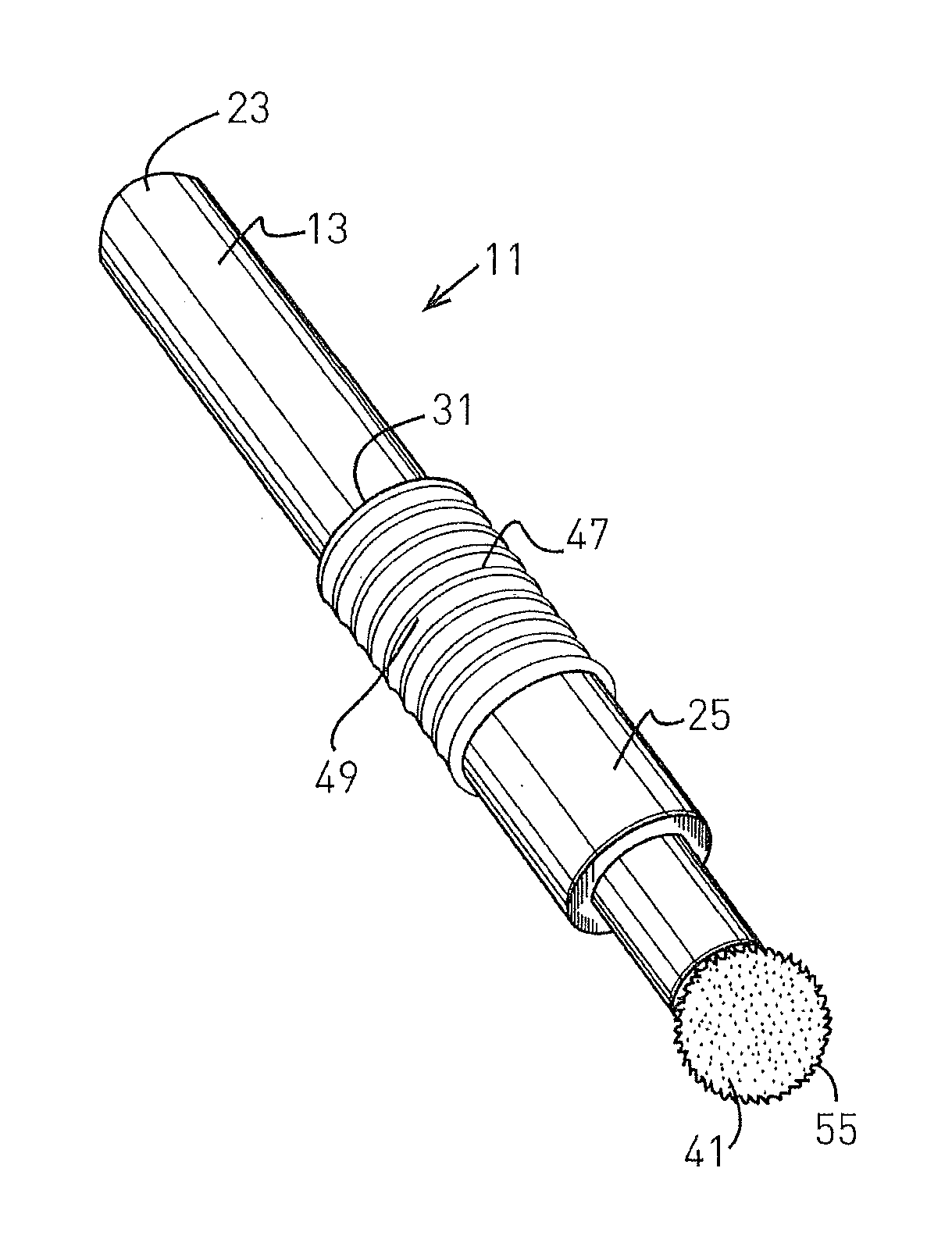
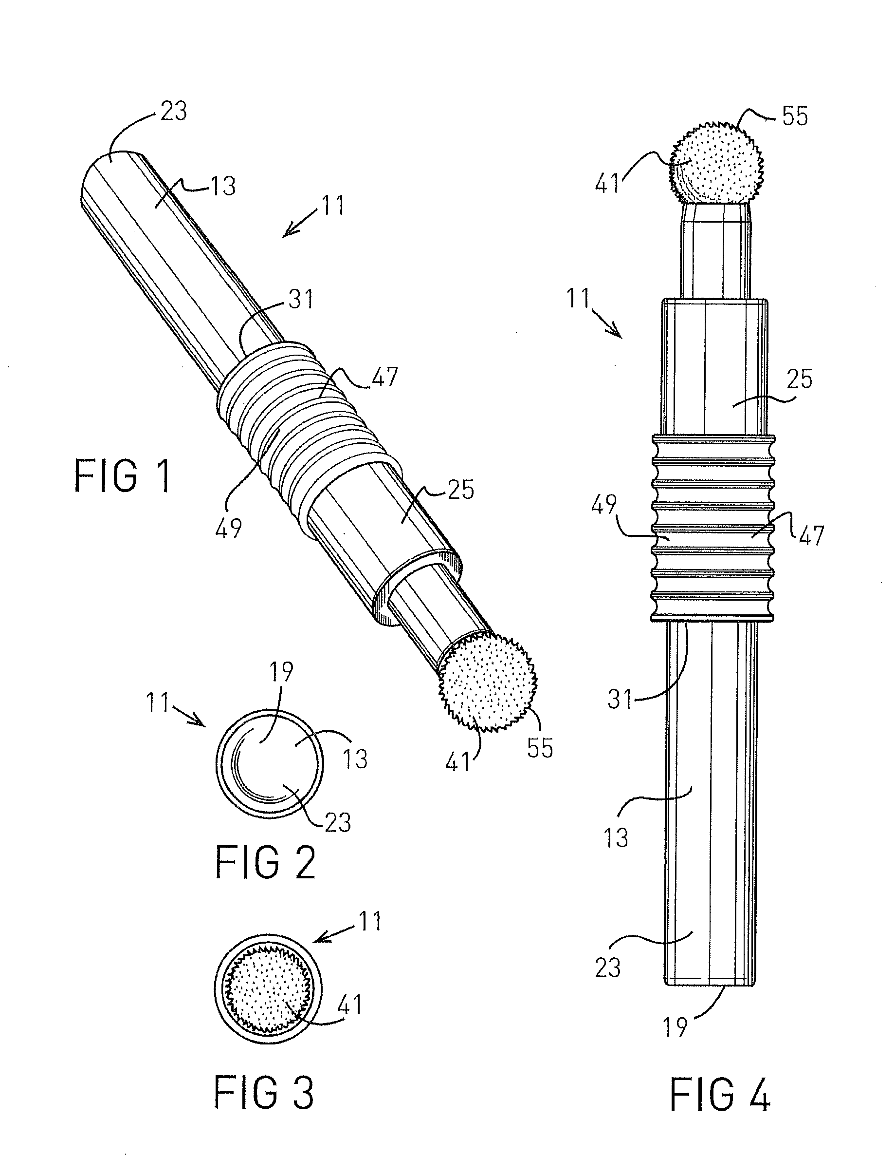
Single and multiple use applicator for volatile fluids having a protective device for guarding against being cut by glass shards formed within the applicator
- Summary
- Abstract
- Description
- Claims
- Application Information
AI Technical Summary
Benefits of technology
Problems solved by technology
Method used
Image
Examples
second embodiment
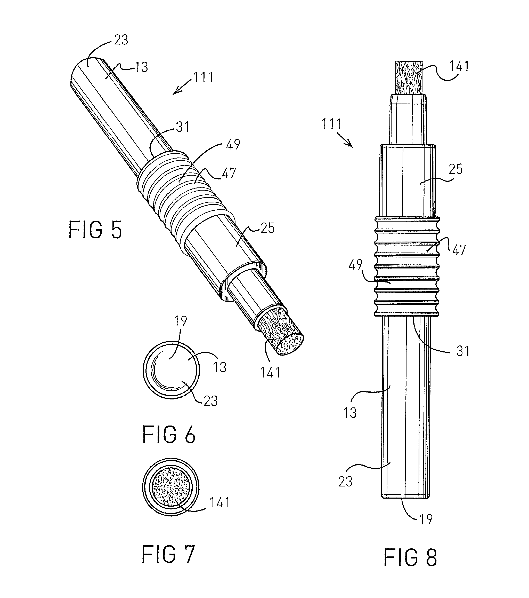
[0054]Turning now to FIGS. 5-8, 19, and 22-24, there is shown the invention. Here, the inventive applicator 111 is substantially the same as the applicator 11, except that a cylindrical dauber 141 is used in the applicator 111 rather than the dauber 41 and needle-like member 43 used in the applicator 11. Preferably, the cylindrical dauber 141 comprises a plurality of fiber strands, in side by side relation forming a porous cylindrical structure. The fiber strands are of any suitable synthetic material, such as polyester fiber, compatible with the fluid 16 to be carried and dispensed from the applicator 111. The dauber 141 preferably is mounted on the second end 33 of the dispensing member 25 by press-fitting a portion of the dauber 141 into the passageway 29 at the second end 33 of the dispensing member 25 so that a portion of the dauber 141 protrudes from the passageway 29. Also, an adhesive may be applied between a portion of dauber 141 and the portion of the dispensing member 25 ...
third embodiment
[0057]Turning now to FIGS. 9-12, 20, and 22-24, there is shown the invention. Here, the inventive applicator 211 is substantially the same as the applicator 111, except that a dauber 241 is used in the applicator 211 rather than the dauber 141 used in the applicator 111. Preferably, the dauber 241 is the same as the dauber 141, except the end portion 257 of the dauber 241 flares radially outwardly as shown in the drawings. The structure of dauber 241 is described in detail in my U.S. Pat. No. 7,004,657, which is hereby incorporated herein by reference. The dauber 241 is mounted on the applicator 211 in the same manner that the dauber 141 is mounted on the applicator 111. The applicator 211 operates in substantially the same manner as the applicator 111.
fourth embodiment
[0058]Turning now to FIGS. 13-17, 21, and 22-26, there is shown the invention. Here, the invention applicator 311 is substantially the same as the applicator 111, except that a dauber 341 is used in the applicator 311 rather than the dauber 141 used in the applicator 111, and a dauber holding device 359 is used in the applicator 311 for holding the dauber 341 and for mounting the dauber 341 onto the dispensing member 25 of the applicator 311. In this embodiment of the invention, the dauber 341 is substantially a larger version of the dauber 141, which preferably is mounted onto the dauber holding device 359 by being press-fit into an trough-like shaped or up-side-down saddle shaped portion 361 of the dauber holding device 359. An adhesive also may be used between the dauber 341 and the portion 361 of the dauber holding device 359 to hold the dauber 341 in place. The dauber holding device 359 also has a cylindrical hollow tube portion 363 that is integral with and extends away from t...
PUM
 Abstract
Description
Claims
Application Information
 - R&D
- Intellectual Property
- Life Sciences
- Materials
- Tech Scout
- Unparalleled Data Quality
- Higher Quality Content
- 60% Fewer Hallucinations
Browse by: Latest US Patents, China's latest patents, Technical Efficacy Thesaurus, Application Domain, Technology Topic, Popular Technical Reports.
© 2025 PatSnap. All rights reserved.Legal|Privacy policy|Modern Slavery Act Transparency Statement|Sitemap|About US| Contact US: help@patsnap.com


