
Functional element in the form of a press-in element

Active Publication Date: 2014-01-02
PROFIL VERBINDUNGSTECHN
View PDF10 Cites 5 Cited by
  • Summary
  • Abstract
  • Description
  • Claims
  • Application Information

AI Technical Summary

Benefits of technology

The technical effect of this patent is to offer a functional element in the form of a press-in element that can be manufactured without problems and offer appropriate security against rotation and axial press-out resistance.

Problems solved by technology

This can lead to loosening of the functional element in the individual sheet metal parts, which is disadvantageous for the later processing.
Through this the danger of loosening of the functional element in the sheet metal part, or of failure of connection between the sheet metal part and the functional element exists when the press-out resistance and the button-out resistance are not guaranteed to the required degree.

Method used


Image

  • Functional element in the form of a press-in element
  • Functional element in the form of a press-in element
  • Functional element in the form of a press-in element

Examples


Embodiment Construction

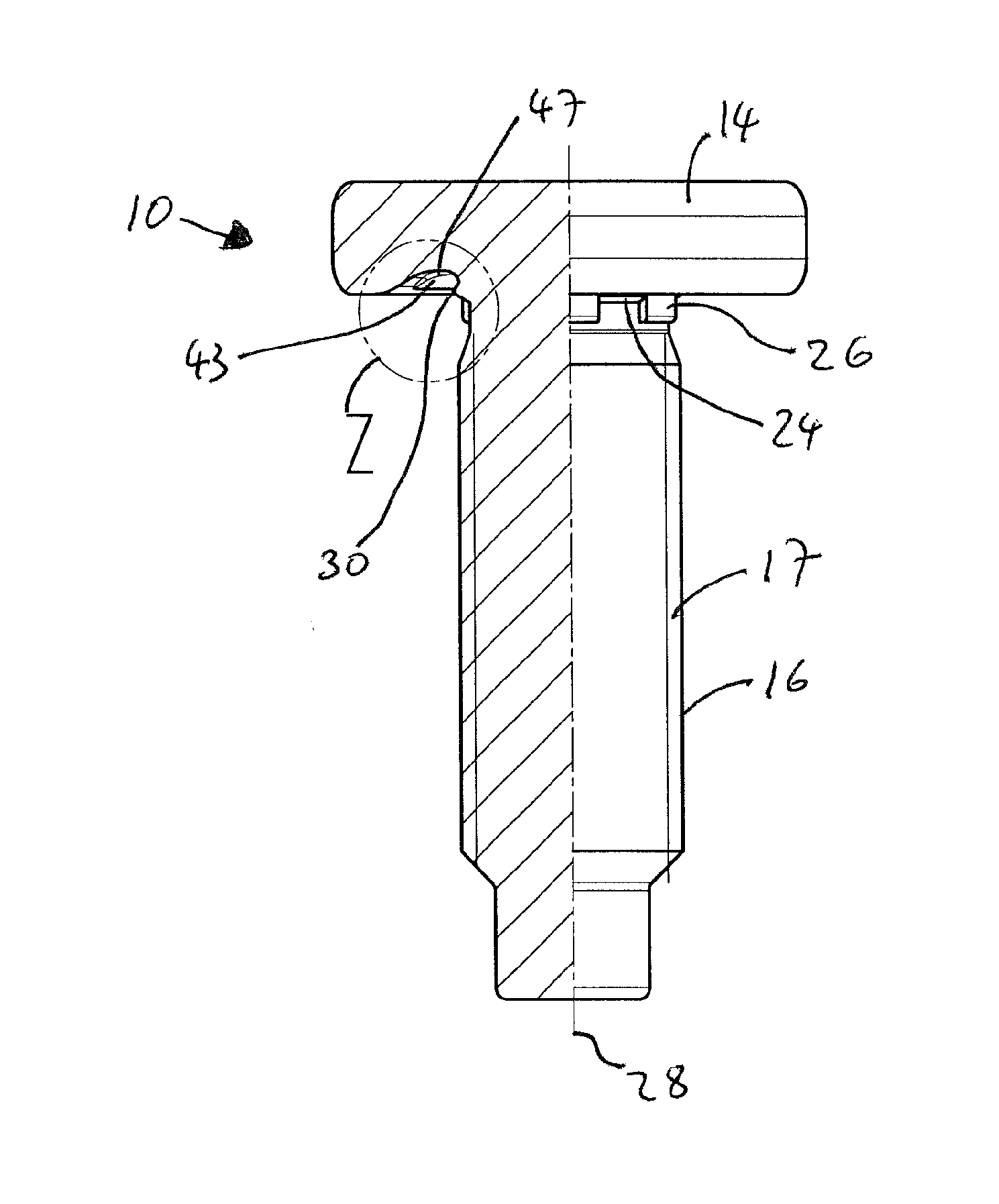
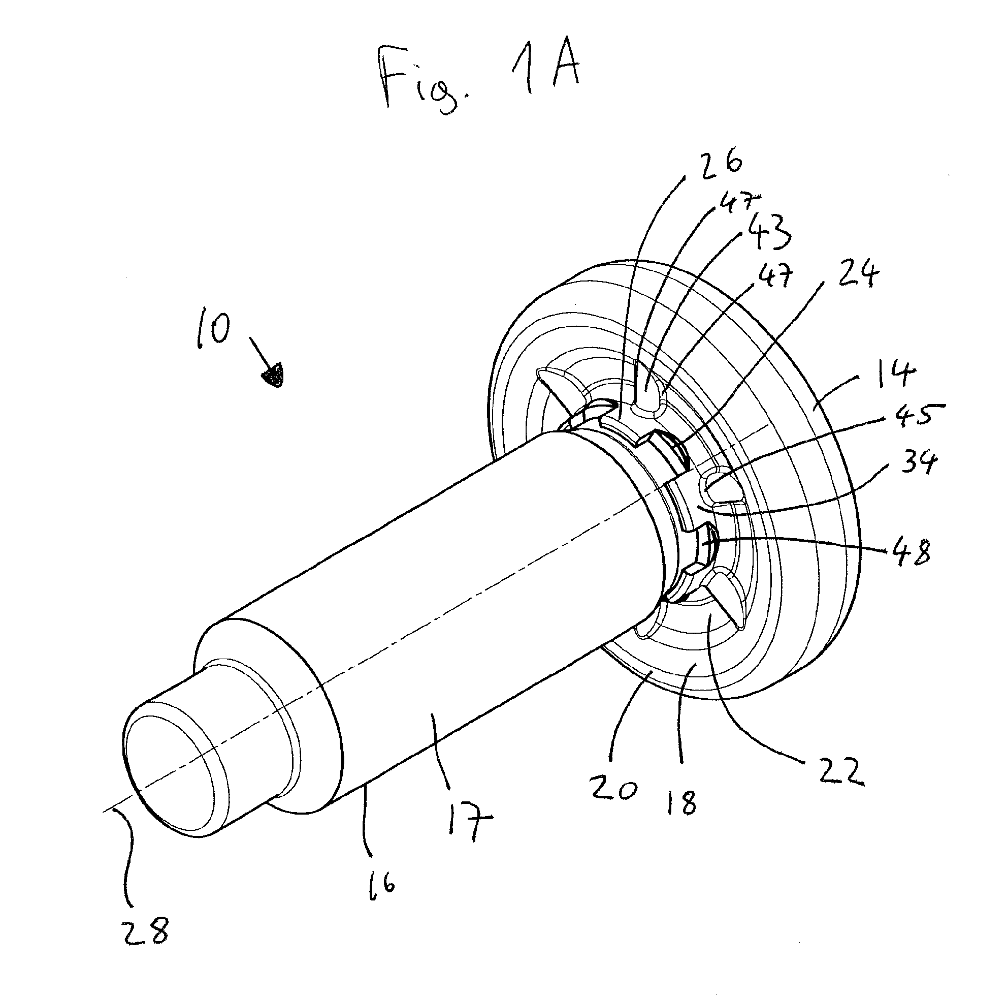
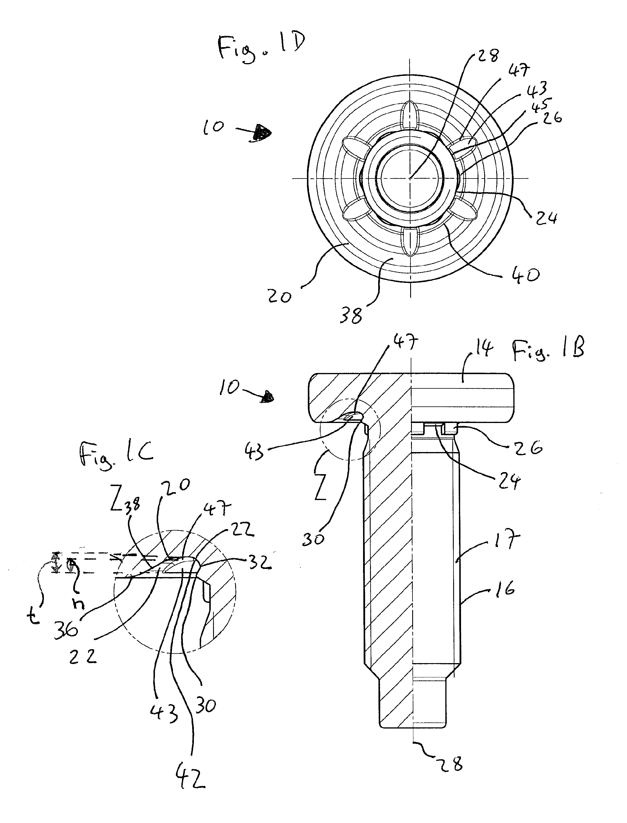
[0057]According to FIGS. 1A to 1D a functional element 10 is shown there in the form of a press-in element which is designed for attachment to the sheet metal part 12 or 12′ in accordance with FIGS. 2A to 2C and 3A to 3C. The functional element 10 has a head part 14 and a shaft part 16. The head part 14 has at the side 18 adjacent to the shaft part 16 a ring-like sheet metal contact surface 20 and within this a ring-like axial recess 22 which surrounds the shaft part at the transition from the head part into the shaft part 16. Furthermore, the shaft part 16 has in this example six preferably distributed radial recesses 24 extending in the axial direction and between them likewise six axially extending and radially projecting noses 26 which alternate with the radial recesses around the central longitudinal axis 28 of the bolt element. At the positions of the radial recesses 24 raised material portions 30 are present at their axial ends adjacent to the head part which form undercuts 3...


PUM


Abstract

A functional element in the form of a press-in element for attachment to a sheet metal part is disclosed which has a head part and a shaft part, the head part has a ring-like sheet metal contact surface within which is a ring-like axial recess which surrounds the shaft part at the transition of the head part into the shaft part. The shaft part has a plurality of peripherally distributed radial recesses extending in the axial direction between which are axially extending and radially projecting noses having raised material portions which form undercuts with the head part in the region of the ring-like recess, the undercuts being present at the positions of the radial recesses at their axial ends adjacent to the head part. Radially extending ribs providing security against rotation, or other anti-rotation security features, are provided in the base region of the ring-like recess.

Description

FIELD OF THE INVENTION[0001]The present invention relates to a functional element in the form of a press-in element for attachment to a sheet metal part. The functional element can either be formed as a male element or as a female element. As a male element a bolt element can be considered whose shaft part is provided with a thread, or an element whose shaft part is provided with a mount for a clip or the like, or an element whose shaft part is made cylindrical and serves as a journal for a component rotatable on an element.BACKGROUND OF THE INVENTION[0002]For a female element a nut element can principally be considered, i.e. an element having an internal thread, with the shaft part being able to be formed as a piercing section so that a self-piercing nut element is present. The thread does not have to be pre-manufactured but rather could be produced after the attachment of the nut element to a sheet metal part by means of a thread forming or thread cutting screw. The female element...

Claims


Application Information

Patent Timeline
IPC IPC(8): F16B19/00B21K1/46
CPCF16B37/068F16B19/00B21K1/46
Inventor BABEJ, JIRI
Owner PROFIL VERBINDUNGSTECHN
Learn More