CPP-type magnetoresistive element including spacer layer

a magnetoresistive element and spacer layer technology, applied in the field of magnetoresistive elements, can solve the problems of limited operation current, small amount of magnetoresistance change of cpp-gmr element, and inability to obtain a sufficiently high value for the magnetoresistance change ratio, and achieve the effect of high mr change ratio

Active Publication Date: 2013-02-19
TDK CORPARATION
View PDF7 Cites 4 Cited by
  • Summary
  • Abstract
  • Description
  • Claims
  • Application Information

AI Technical Summary

Benefits of technology

[0020]It is an object of the present invention to provide a magnetoresistive element that can provide a resistance of an appropriate value and a sufficiently high MR change ratio, and to a thin-film magnetic head, a head assembly, and a magnetic recording device that each include such a magnetoresistive element.
[0027]In the magnetoresistive element of the present invention, and the thin-film magnetic head and the magnetic recording device each including the magnetoresistive element, the spacer layer of the magnetoresistive element includes the nonmagnetic metal layer made of Cu, the first oxide semiconductor layer made of a Ga oxide semiconductor, and the second oxide semiconductor layer made of a Zn oxide semiconductor. The nonmagnetic metal layer and the first and second oxide semiconductor layers have thicknesses in respective predetermined ranges. Consequently, according to the present invention, it is possible to make the resistance of the magnetoresistive element appropriate in value and make the MR change ratio sufficiently high. The nonmagnetic metal layer has the function of preventing oxidation of one of the ferromagnetic layers that is in contact with the spacer layer, thereby preventing the characteristic degradation of the one of the ferromagnetic layers.

Problems solved by technology

Such a read head has the problem that the operating current is limited in order to ensure reliability.
A typical CPP-GMR element, however, shows a small magnetoresistance change amount because the spacer layer, i.e., a nonmagnetic conductive layer, has low resistance.
Accordingly, there is a problem that it is not possible to obtain a sufficiently high value for the magnetoresistance change ratio, i.e., the ratio of the magnetoresistance change to the resistance of the element (hereinafter referred to as MR change ratio).
The high resistance of the TMR element, however, increases the stray capacitance occurring in the TMR element and in the circuits connected thereto, which degrades the high-frequency response of the read head.
The results revealed that it is difficult to make the element resistance appropriate in value and make the MR change ratio sufficiently high if the spacer layer includes only a layer of a single type of oxide semiconductor as the layer formed of an oxide semiconductor.

Method used


Image

  • CPP-type magnetoresistive element including spacer layer
  • CPP-type magnetoresistive element including spacer layer
  • CPP-type magnetoresistive element including spacer layer

Examples


first embodiment

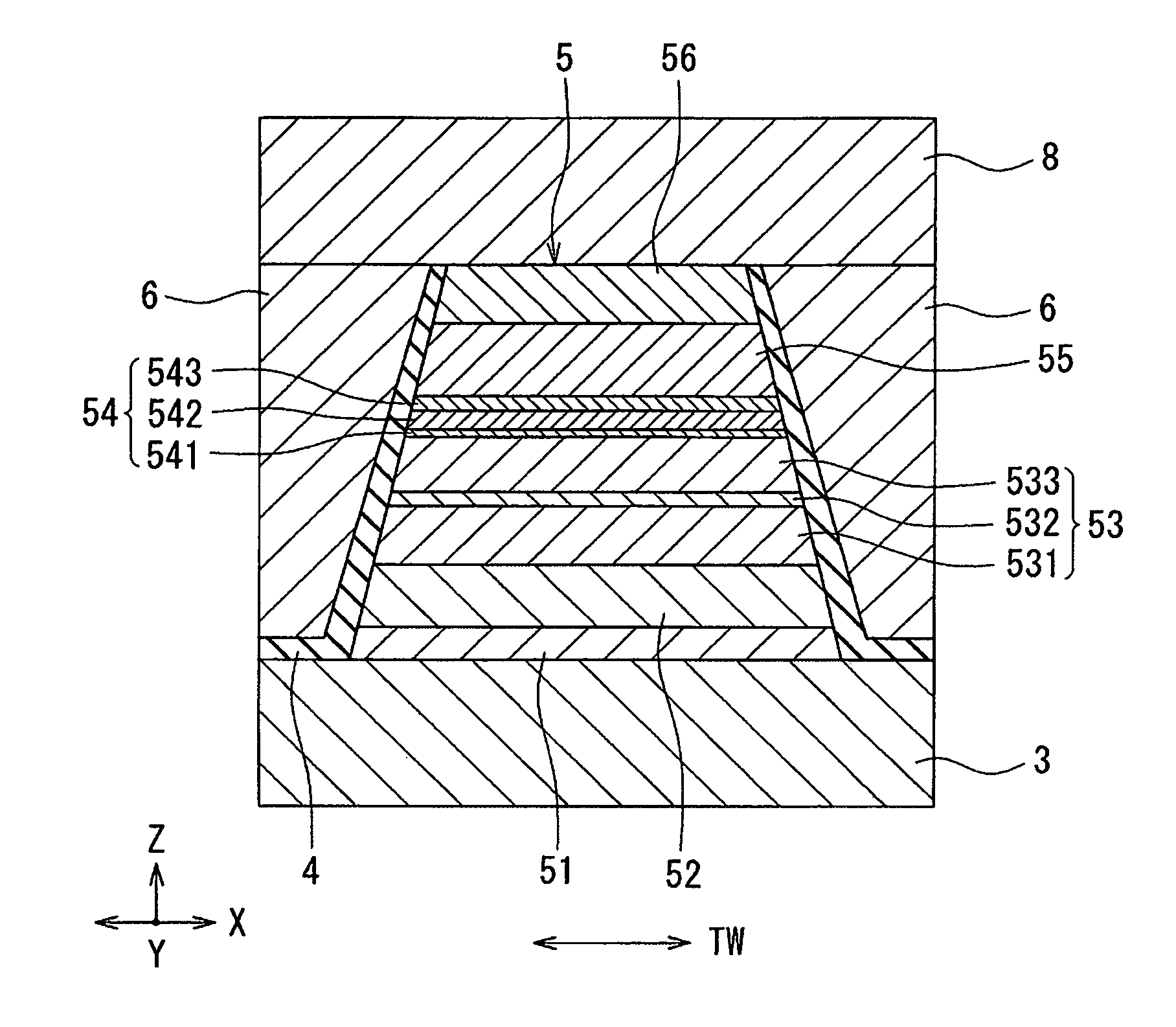
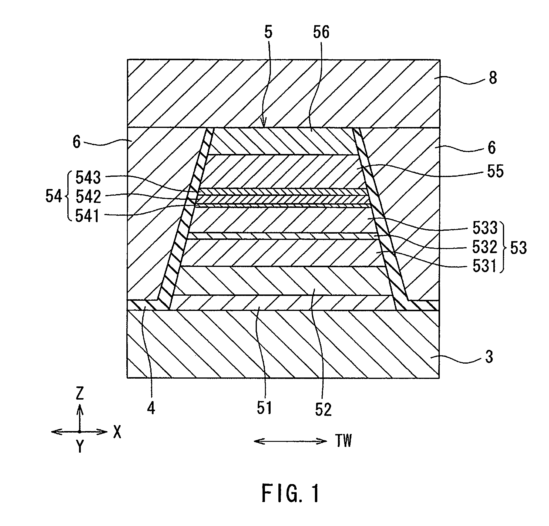
[0046]Embodiments of the present invention will now be described in detail with reference to the drawings. First, with reference to FIG. 4, a description will be given of a slider 210 including a thin-film magnetic head (hereinafter, simply referred to as magnetic head) according to a first embodiment of the invention. The magnetic head according to the present embodiment is for use in perpendicular magnetic recording. In a magnetic recording device, the slider 210 is disposed to face a circular-plate-shaped recording medium (a magnetic disk) that is driven to rotate. In FIG. 4, the X direction is a direction across the tracks of the recording medium, i.e., the track width direction. The Y direction is a direction perpendicular to the surface of the recording medium. The Z direction is the direction of travel of the recording medium as viewed from the slider 210. The X, Y, and Z directions are orthogonal to one another. The slider 210 has a base body 211. The base body 211 is nearly...

second embodiment

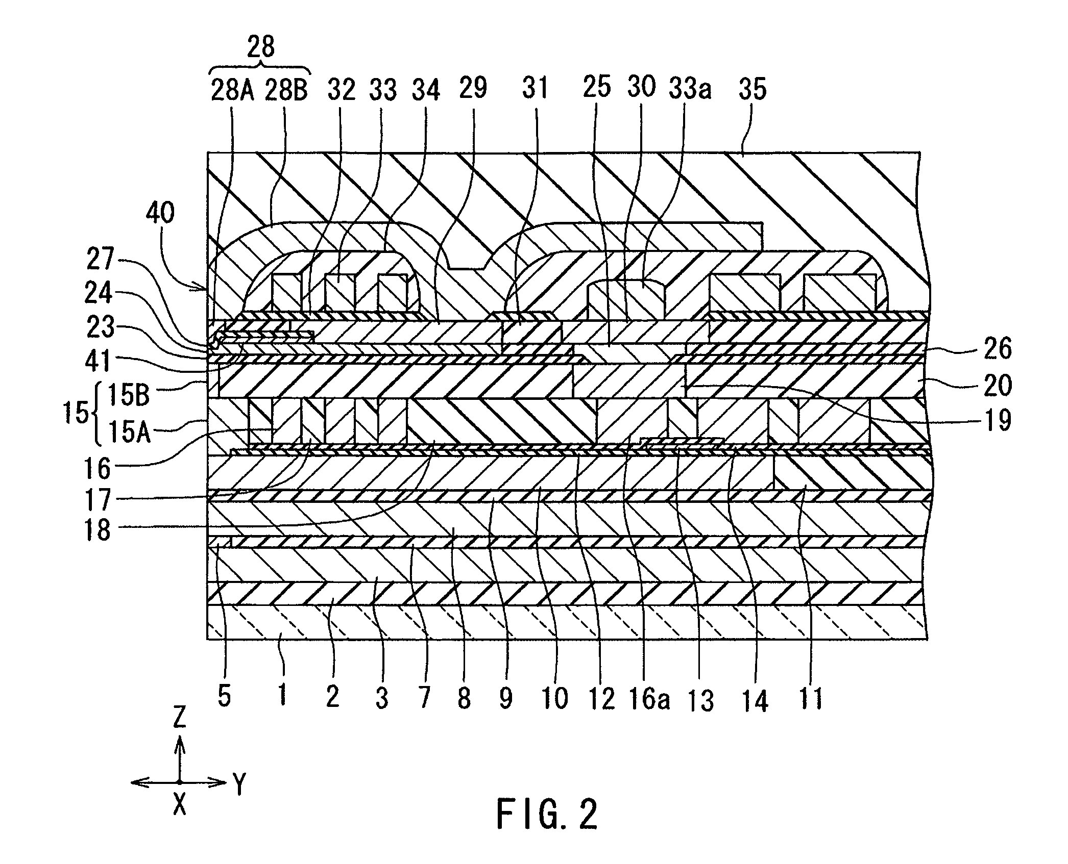
[0134]A second embodiment of the invention will now be described with reference to FIG. 14 to FIG. 17. FIG. 14 is a cross-sectional view showing a cross section of a read head including an MR element according to the present embodiment, the cross section being parallel to the medium facing surface. The read head in the present embodiment has a first read shield portion 93 and a second read shield portion 98 instead of the first read shield 3 and the second read shield 8 of the first embodiment, and has an MR element 105 according to the present embodiment instead of the MR element 5 of the first embodiment. The MR element 105 and the second read shield portion 98 are stacked in this order on the first read shield portion 93. The planar shape (the shape viewed from above) of the MR element 105 is smaller than that of each of the read shield portions 93 and 98. The insulating layer 4 of the present embodiment covers the two sides of the MR element 105 and a rear end of the MR element ...


PUM

PropertyMeasurementUnit
thicknessaaaaaaaaaa
thicknessaaaaaaaaaa
thicknessaaaaaaaaaa

Abstract

An MR element includes a first ferromagnetic layer, a second ferromagnetic layer, and a spacer layer disposed between the first and second ferromagnetic layers. The spacer layer includes a nonmagnetic metal layer, a first oxide semiconductor layer, and a second oxide semiconductor layer that are stacked in this order. The nonmagnetic metal layer is made of Cu, and has a thickness in the range of 0.3 to 1.5 nm. The first oxide semiconductor layer is made of a Ga oxide semiconductor, and has a thickness in the range of 0.5 to 2.0 nm. The second oxide semiconductor layer is made of a Zn oxide semiconductor, and has a thickness in the range of 0.1 to 1.0 nm.

Description

BACKGROUND OF THE INVENTION[0001]1. Field of the Invention[0002]The present invention relates to a magnetoresistive element for use in magnetic recording devices, oscillators, magnetoresistive random access memories (MRAMs), magnetic sensors and the like, and to a thin-film magnetic head, a head assembly, and a magnetic recording device that each include the magnetoresistive element.[0003]2. Description of the Related Art[0004]Recently, magnetic recording devices such as magnetic disk drives have been improved in areal recording density, and thin-film magnetic heads of improved performance have been demanded accordingly. Among the thin-film magnetic heads, a composite thin-film magnetic head has been used widely. The composite thin-film magnetic head has such a structure that a read head including a magnetoresistive element (hereinafter, also referred to as MR element) for reading and a write head including an induction-type electromagnetic transducer for writing are stacked on a su...

Claims


Application Information

Patent Timeline
Patent Type & Authority Patents(United States)
IPC IPC(8): G11B5/33
CPCB82Y10/00B82Y25/00G11B5/3932H01F10/193H01F10/3254H01L43/10G11B2005/3996H10N50/85
Inventor MATSUZAWA, HIRONOBUTSUCHIYA, YOSHIHIRO
Owner TDK CORPARATION
Why Eureka
Try Eureka