Intra spinous process and method of bone graft placement

a bone graft and spinous technology, applied in the field of spinal fixation plates, can solve the problems of inability to use, and inability to perform posterior stabilization

Inactive Publication Date: 2014-01-02
IINN
View PDF5 Cites 17 Cited by
  • Summary
  • Abstract
  • Description
  • Claims
  • Application Information

AI Technical Summary

Problems solved by technology

It has not been possible, however, to perform posterior stabilization with the type of spinal fixation plate that has proven effective in anterior stabilization; that is, a solid plate which anchors to the pedicles of two or more vertebrae by means of bone screws or other fasteners.
Such spinous process clamps have important drawbacks.
They cannot be employed when spinous processes are damaged by disease or trauma or have been removed during the course of therapeutic laminotomy or laminectomy.
Spinous process clamps can also be difficult to secure when there are large anatomical differences between neighboring spinous processes.
The clamps also lack the physical robustness of a solid plate that mechanically couples two adjoining vertebrae by means of a multiplicity of screws, an arrangement that provides efficient load sharing and transfer and attendant stability.
Furthermore, spinous process clamps join and immobilize adjacent spinous processes and are therefore liable to fracture the spinous processes by exerting torque on the processes during normal body movements and, more dramatically, during a fall.
In addition, the spinal fixation devices of the prior art do not provide structures that promote fusion by encouraging the adhesion and growth of grafted bone.

Method used


Image

  • Intra spinous process and method of bone graft placement
  • Intra spinous process and method of bone graft placement
  • Intra spinous process and method of bone graft placement

Examples


Embodiment Construction

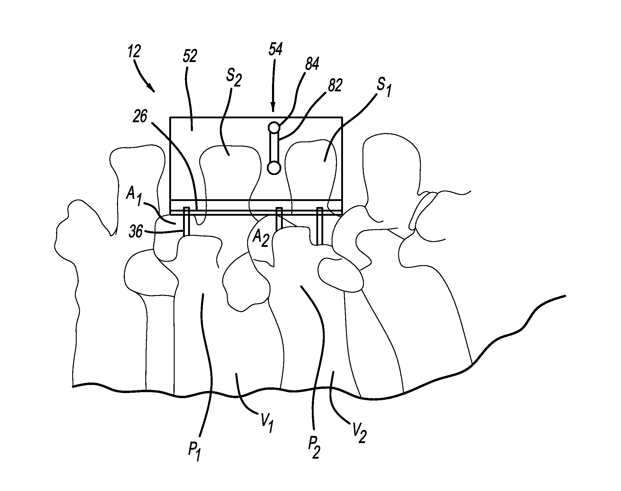
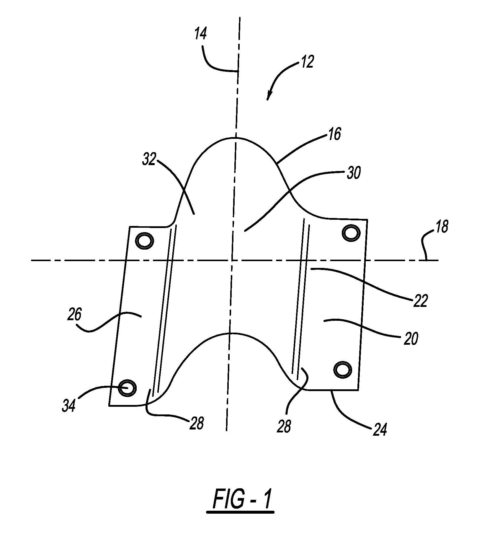
[0037]A spinal fixation plate constructed in accordance with the present invention is generally indicated by 12 in the figures. As shown in FIG. 1, generally the fixation plate 12 is a substantially elongated plate body 12 with a longitudinal axis 14 defined by two opposed ends 16, and a lateral axis 18 defined by two opposed sides 20. The fixation plate 12 includes an upper surface 22, and an opposed lower surface 24. The fixation plate 12 also includes flattened flanges 26, each flange extending along each of the sides 20. The flanges 26 are interconnected by an arcuate process 28.

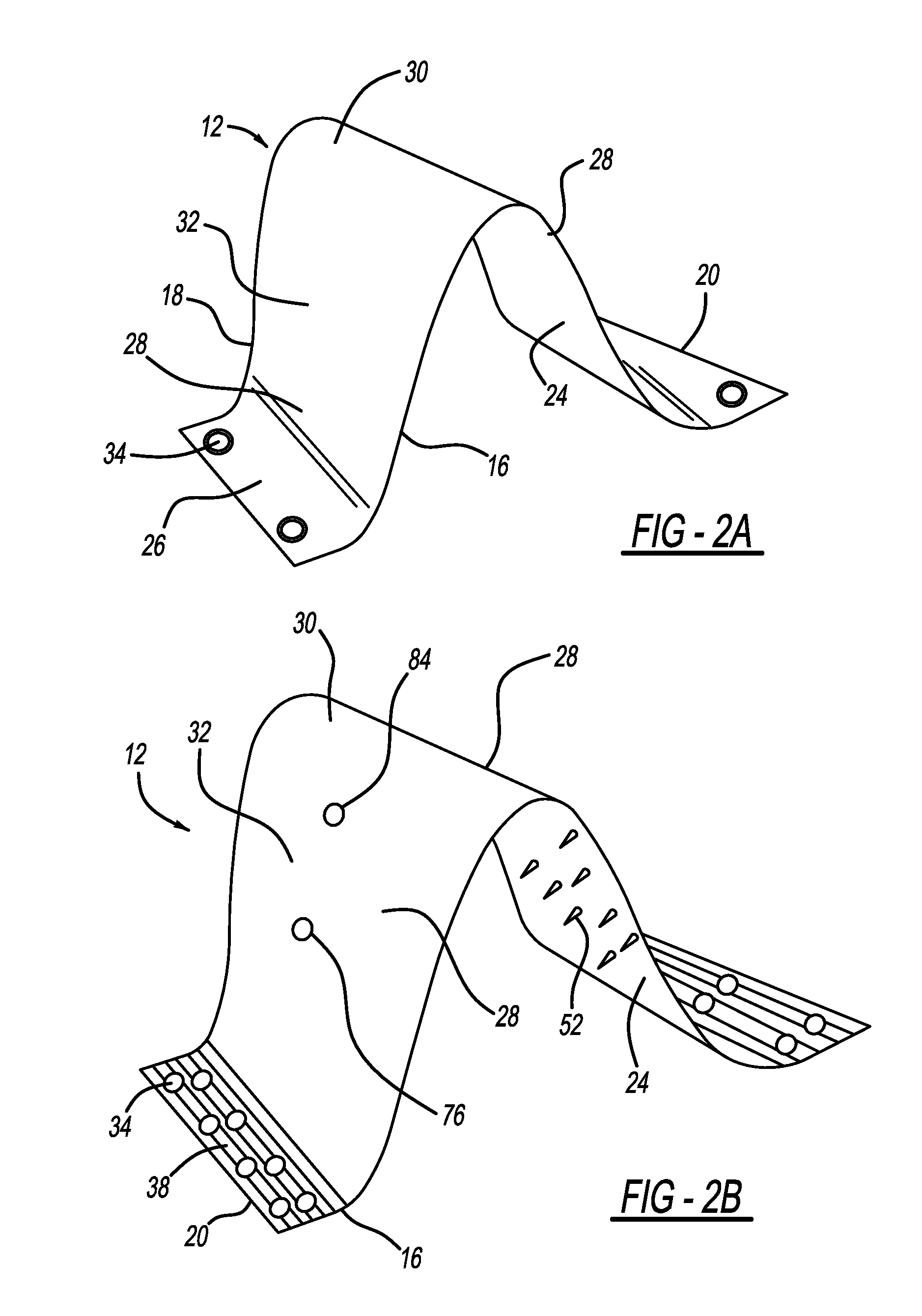
[0038]The arcuate process 28 is convex in cross section and describes an arc with its apex 30 generally at the midpoint of the lateral axis 18, indicated in FIG. 2. The arcuate process extends along the length of the longitudinal axis 14 of the fixation plate 12. The shoulders 32 of the arcuate process 28 slope outward to join seamlessly with the flanges 26. The flanges 26 are generally flat and oriented...


PUM


Abstract

A spinal fixation plate for posterior fixation, including a plate body having flattened flanges extending along sides of the plate body, the flanges being interconnected by a convex arcuate process. A method of fixing vertebrae, including the steps of disposing a spinal fixation plate upon dorsal surfaces of adjoining vertebrae, wherein flanges of the spinal fixation plate extend parallel to the spinal column and rest upon superior articular processes of the adjoining vertebrae, and anchoring the spinal fixation plate to the vertebrae with at least one fastener by disposing the fastener through at least one aperture of the spinal fixation plate into the vertebrae.

Description

TECHNICAL FIELD[0001]The present invention relates to spinal fixation plates. More specifically, the present invention relates to a spinal fixation plate that includes an arcuate portion to circumvent the spinous processes and allow the plate to be anchored on the dorsum of the spine, and to the method of using this plate in spinal fusion involving bone grafts.BACKGROUND OF THE INVENTION[0002]Spinal fixation has become a common approach in treating spinal disorders, fractures, and for fusion of vertebrae. Surgery of this kind is indicated when the patient experiences chronic pain due to abnormal motion of the vertebrae, where immobilizing the vertebrae can provide pain relief. The aim of the surgery is to stabilize adjacent vertebrae that are the foci for a variety of medical conditions. Spinal fixation can be used alone or in conjunction with spinal fusion in the treatment of degenerative disc disease and other conditions, including spinal disc herniation, discogenic pain, spinal t...

Claims


Application Information

Patent Timeline
Patent Type & Authority Applications(United States)
IPC IPC(8): A61B17/70A61B17/88
CPCA61B17/7062A61B17/88A61B17/7059A61B17/80A61B17/8085
Inventor SHAH, JAWAD A.SMITH, RICHARD H.IQBAL, AMER
Owner IINN
Why Eureka
Try Eureka