Axial Gap Rotating-Electric Machine

a technology of rotating electric machines and axial gaps, which is applied in the direction of dynamo-electric components, synchronous machines with stationary armatures and rotating magnets, cooling/ventilation arrangements, etc., and can solve problems such as electric corrosion of bearings

Active Publication Date: 2014-01-09
HITACHI LTD
View PDF3 Cites 42 Cited by
  • Summary
  • Abstract
  • Description
  • Claims
  • Application Information

AI Technical Summary

Benefits of technology

[0012]According to the invention, the stator core may be grounded without complicating the structure.
[0013]The subject, the configuration, and the effects other than those described above will be apparent from the description of the embodiments given below.

Problems solved by technology

In contrast, when the stator is held by a mold resin, a problem of electrical corrosion of the bearing arises.

Method used


Image

  • Axial Gap Rotating-Electric Machine
  • Axial Gap Rotating-Electric Machine
  • Axial Gap Rotating-Electric Machine

Examples


example 1

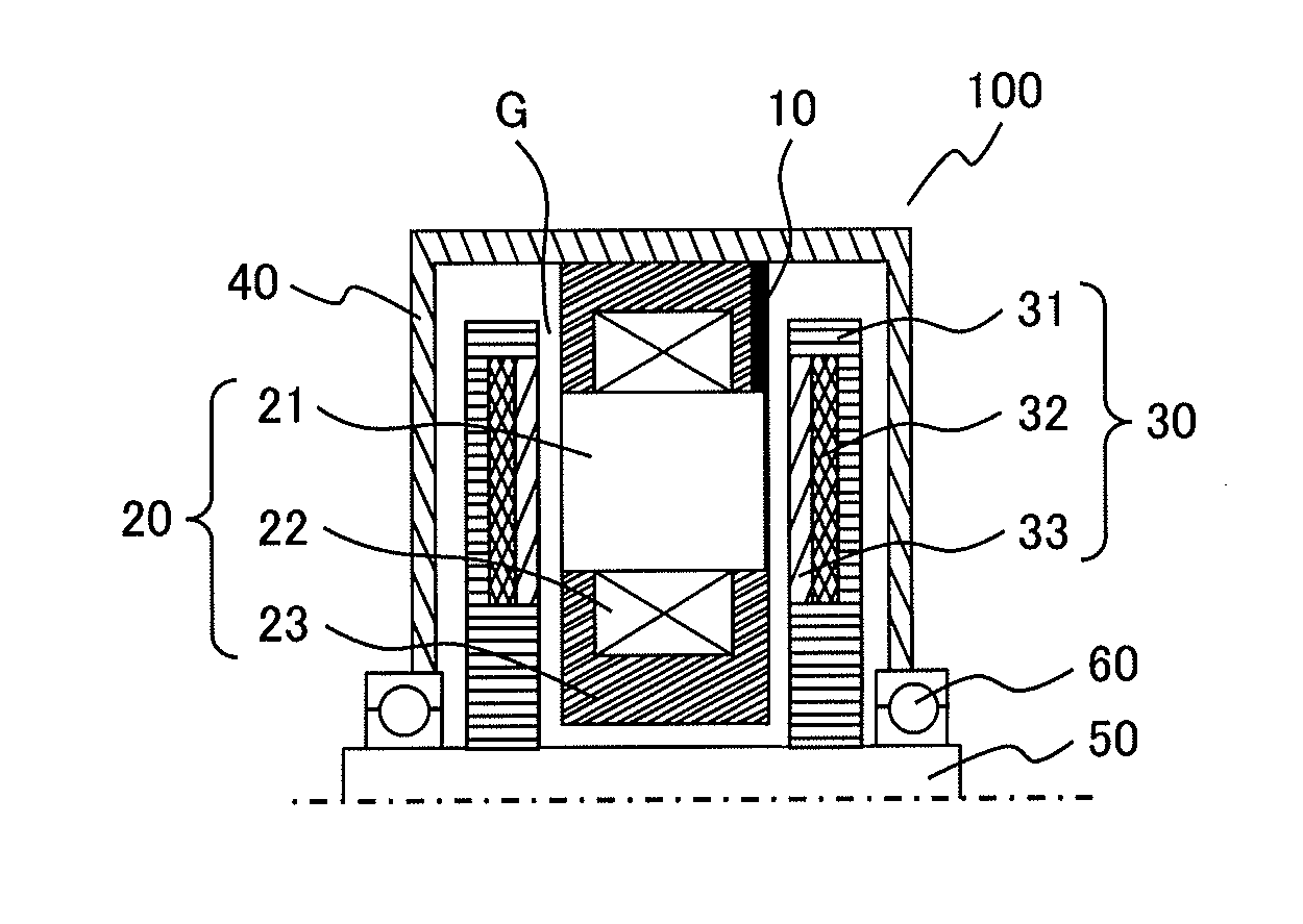
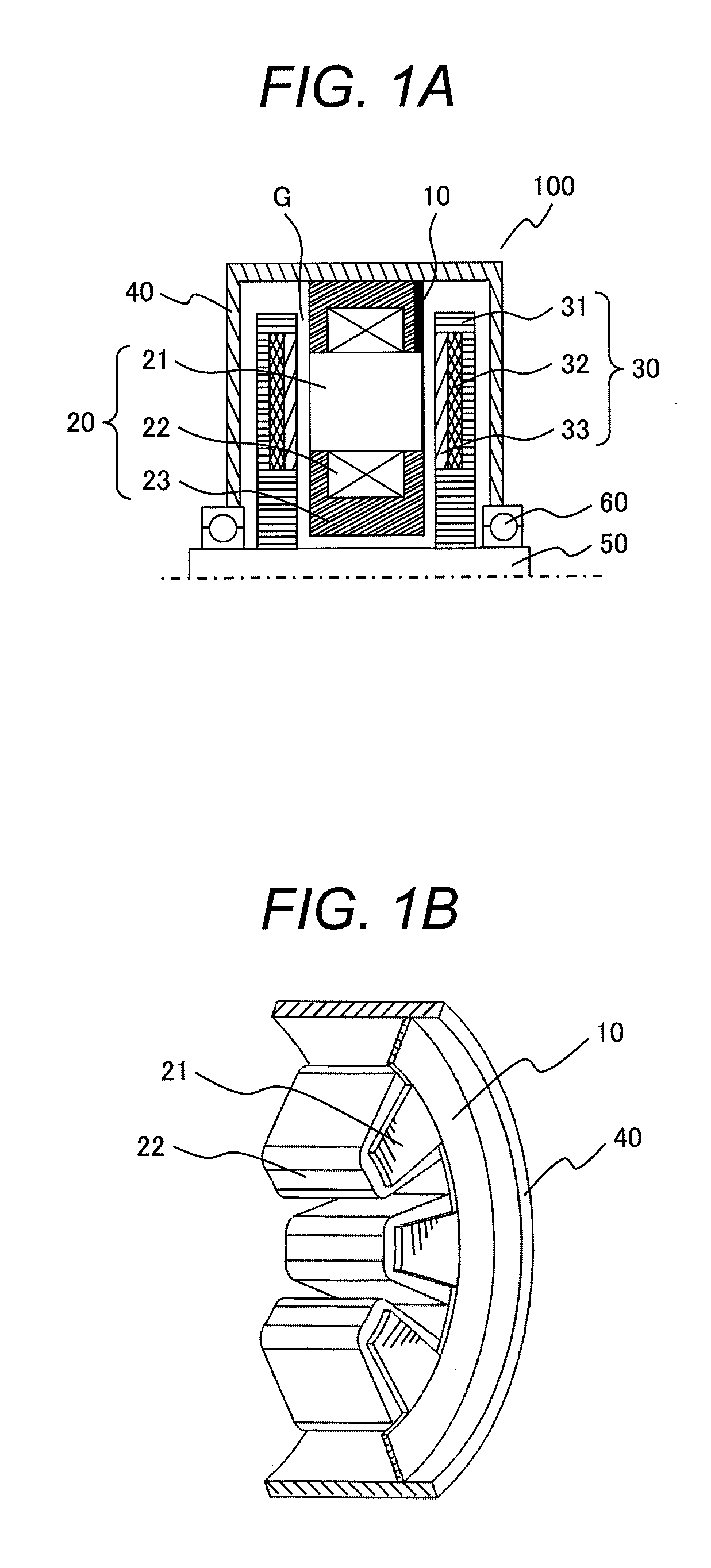
[0038]FIG. 1A is a cross-sectional view illustrating an example of the two-rotor one-stator axial gap motor as Example 1. FIG. 13 is a perspective view of the stator 20 of FIG. 1A. In FIG. 1B, illustration of the mold resin 23 is omitted.

[0039]In Example 1, the stator is configured so that the stator cores 21 partly protrude in the axial direction (the direction of the axis of rotation of the motor) from the coils 22. A ring-shaped non-magnetic or paramagnetic conductive member 10 is arranged between the outer peripheral surfaces of the protruding portions of the stator cores 21 and the inner peripheral surface of the housing 40. For example, aluminum alloy is used as a non-magnetic conductive member. Although a magnetic material may be used as the conductive member, a non-magnetic conductive member is preferably used for allowing the magnetic field to pass effectively through the stator cores.

[0040]The inner peripheral surface of the link-shaped conductive member 10 comes into cont...

example 2

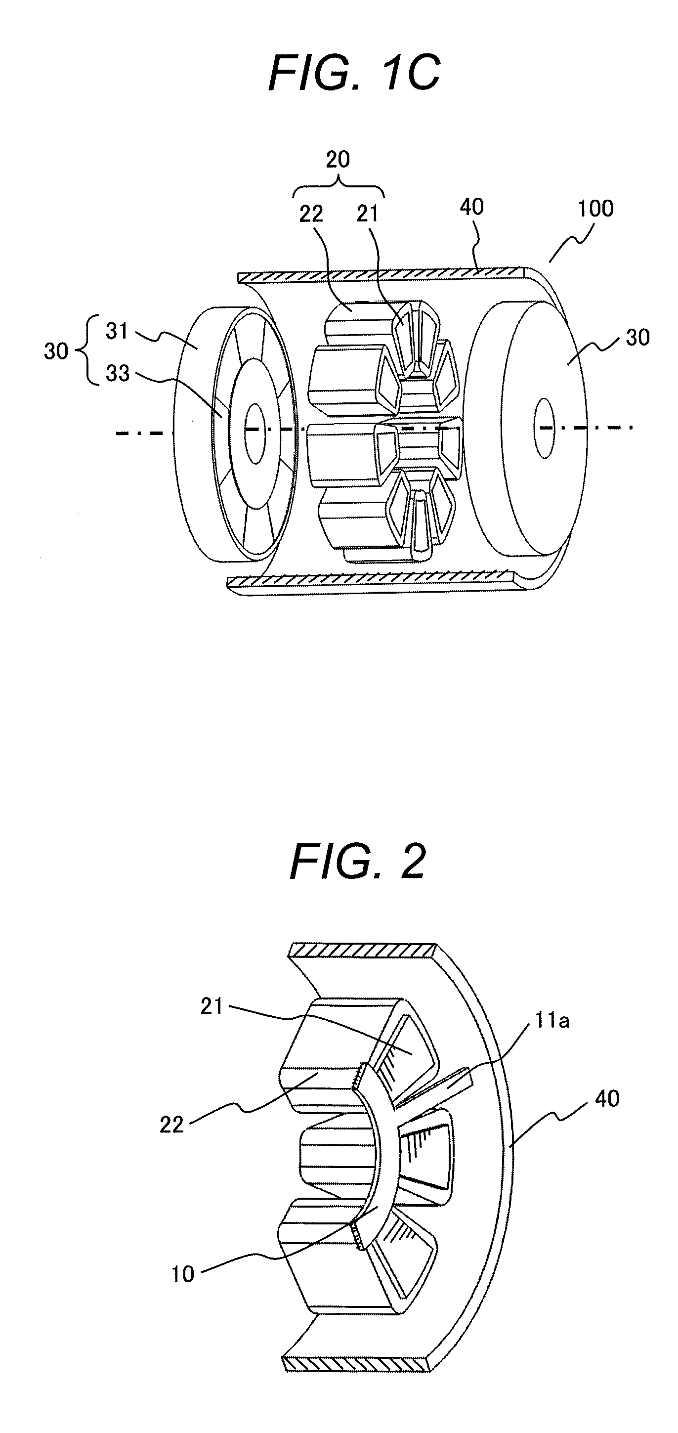
[0045]FIG. 2 is a drawing illustrating a structure of a stator of the two-rotor one-stator axial gap motor as Example 2. The same portions as Example 1 are denoted by the same reference numerals, and the description thereof is omitted.

[0046]In Example 2, the ring-shaped non-magnetic conductive member 10 is arranged on the inner peripheral sides of the stator cores 21. The outer peripheral surface of the link-shaped conductive member 10 comes into contact with the inner peripheral surfaces of all of the protruding portions of a plurality of the stator cores 21 arranged in the circumferential direction. Furthermore, at least one projecting portion 11a extending in the radial direction is provided on the outer peripheral surface (the outer peripheral side) of the ring-shaped conductive member 10 and a distal end of the projecting portion 11a comes into contact with the inner peripheral surface of the housing 40. In other words, the plurality of the stator cores 21 come into contact wit...

example 3

[0052]FIG. 3 is a drawing illustrating a structure of a stator of the two-rotor one-stator axial gap motor as Example 3. The same portions as Example 1 are denoted by the same reference numerals, and the description thereof is omitted.

[0053]In Example 3, a plurality of the projecting portions 11b are provided on the inner peripheral side of the conductive member of Example 1. The respective projecting portions 11b come into contact with the side surface of the protruding portions of the stator cores 21 between the protruding portions of the stator cores 21.

[0054]In Example 3 as well, the same effect as Example 1 is obtained. In particular, in Example 3, a plurality of the stator cores 21 come into contact with the conductive member 10 (the projecting portions 11b) also on the side surfaces of the protruding portions in addition to the outer peripheral surfaces of the protruding portions, and hence the contact properties between the stator cores 21 and the conductive member 10 may be...


PUM


Abstract

An axial gap rotating-electric machine includes a stator, a rotor arranged via an air gap in the direction of an axis of rotation of a rotating-electric machine with respect to the stator, and a housing configured to accommodate the stator and the rotor, and the stator includes a plurality of stator cores arranged in the circumferential direction, coils configured to wind the peripheries of the respective stator cores, and a resin for molding the plurality of stator cores wound with the coils, and the stator cores each include a protruding portion protruding partly from the coil in the direction of axis of rotation, and a conductive member is provided so as to come into contact with peripheral surfaces of the protruding portions of the stator cores, and grounding is achieved by the conductive member.

Description

CLAIM OF PRIORITY[0001]The present application claims priority from Japanese Patent application serial No. 2012-152091, filed on Jul. 6, 2012, the content of which is hereby incorporated by reference into this application.TECHNICAL FIELD[0002]The present invention relates to an axial gap rotating-electric machine and, more specifically, to an earth structure of a stator core of an axial gap rotating-electric machine in which a stator is held by a mold resin.BACKGROUND ART[0003]Axial gap rotating-electric machines include a two-rotor one-stator axial gap rotating-electric machine having a structure including a pair of disk-shaped rotors arranged in the direction of the rotating shaft of the rotating-electric machine so as to face each other, and a stator interposed between the pair of rotors with a predetermined gap therebetween. The rotor includes a rotor core and one or a plurality of magnets arranged in the circumferential direction, and the stator includes a plurality of stator c...

Claims


Application Information

Patent Timeline
Patent Type & Authority Applications(United States)
IPC IPC(8): H02K11/00
CPCH02K11/0089H02K21/24H02K1/182H02K5/08H02K11/40H02K9/223
Inventor DEGUCHI, KENTATOKOI, HIROOKIWANG, ZHUONANIWASAKI, NORIHISAENOMOTO, YUJI
Owner HITACHI LTD
Why Eureka
Try Eureka