Eureka AIR delivers breakthrough ideas for toughest innovation challenges, trusted by R&D personnel around the world.

Apparatus and method for multiplying frequency of a clock signal

Active Publication Date: 2014-01-09
SILICON INTEGRATED SYSTEMS
View PDF1 Cites 2 Cited by
  • Summary
  • Abstract
  • Description
  • Claims
  • Application Information

AI Technical Summary

Benefits of technology

The patent describes a way to change the frequency of a clock signal using an apparatus that includes an oscillation circuit, a control signal generation circuit, a threshold value generation circuit, and a clock output circuit. The oscillation circuit creates an initial clock signal, the control signal generation circuit compares this signal to a reference signal and generates a first control signal, which is sent to the threshold value generation circuit. The threshold value generation circuit receives the initial clock signal and produces higher and lower threshold values in response to the first control signal. The clock output circuit uses these threshold values to process the comparison between the initial clock signal and the output of the upper or lower threshold value, and the comparison between the initial clock signal and a low level signal, ultimately outputting a final clock signal. The technical effect is to provide a way to change the frequency of a clock signal using a simple apparatus and method.

Problems solved by technology

Over the years, various problems occur as microprocessors become higher in integration and performance.
First, the volume increase of the System-on-Chip (SoC) is caused by the increase in clock skew and clock frequency.
As a result, the period of one cycle is shortened, thereby increasing the burden of jitter.
Second, higher integration requires higher power density, so there is also a need to take a low-power design into consideration.

Method used


Image

  • Apparatus and method for multiplying frequency of a clock signal
  • Apparatus and method for multiplying frequency of a clock signal
  • Apparatus and method for multiplying frequency of a clock signal

Examples


Embodiment Construction

[0022]The detailed features and advantages of the disclosure are described below in great detail through the following embodiments, the content of which is sufficient for those of ordinary skill in the art to understand the technical content of the disclosure and to implement the disclosure accordingly. Based upon the content of the specification, the claims, and the drawings, those of ordinary skill in the art can easily understand the relevant objectives and advantages of the disclosure.

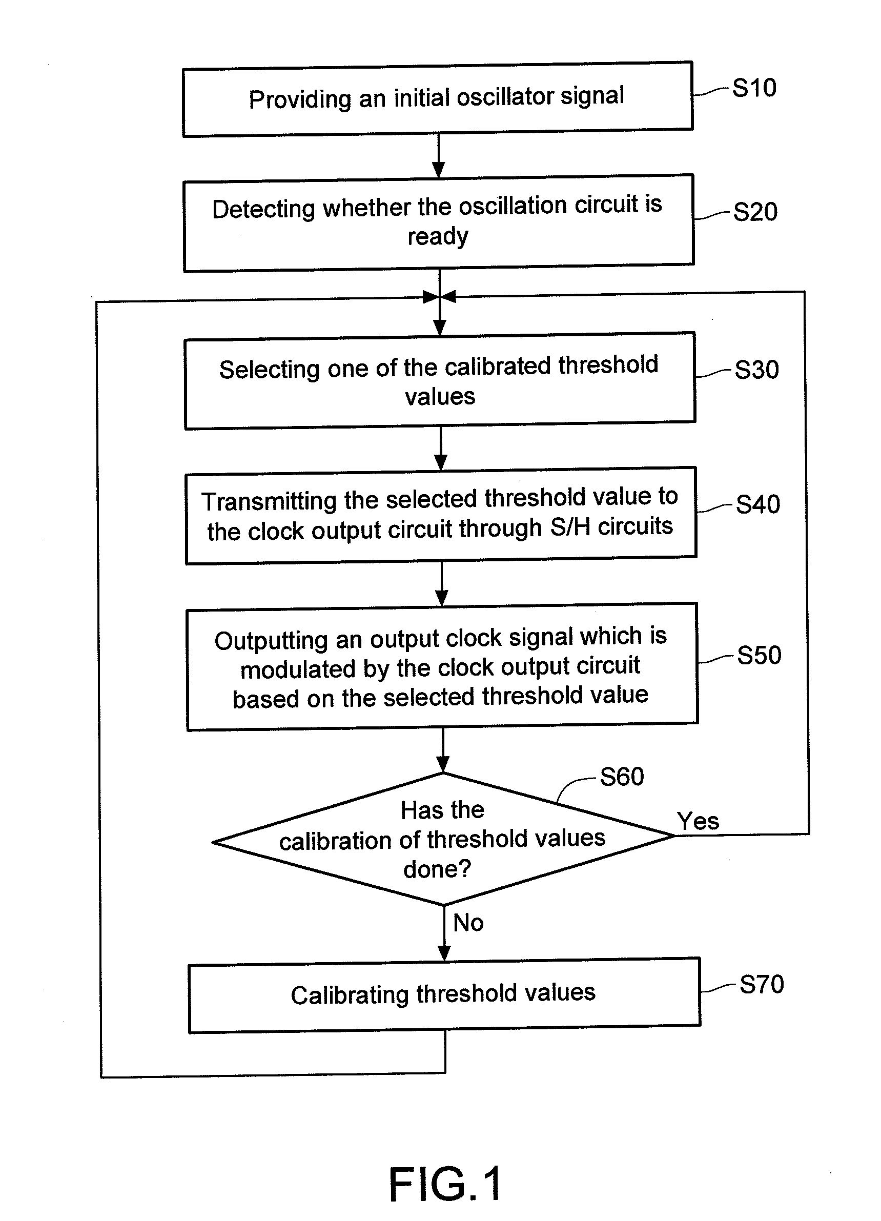
[0023]Referring to FIG. 1, a flow chart of a method for multiplying frequency of a clock signal is shown. Initially, an oscillator signal is provided (step S10). After the oscillator is ready (step S20), one of voltage levels (threshold values) is selected (step S30) and the selected threshold value is transmitted to the clock output circuit through corresponding one of S / H circuits (step S40). The output clock signal is modulated by comparing the initial oscillator signal with different selected t...


PUM


Abstract

An apparatus and method for multiplying frequency of a clock signal are provided, wherein the apparatus provides an initial oscillator signal, compares the initial oscillator signal with a reference signal to generate a first control signal, selectively outputs one of at least one lower threshold value and at least one upper threshold value from a threshold value generation circuit to a clock output circuit according to at least the first control signal, and updates an output clock signal through a digital and logical module processing the comparison of the initial oscillator signal and the selected one of the at least one upper and lower threshold values and the comparison of the initial oscillator signal and a low level signal.

Description

BACKGROUND[0001]1. Technical Field[0002]The disclosure relates to a frequency multiplier, and more particularly to an apparatus and a method for multiplying frequency of a clock signal by automatic calibration.[0003]2. Related Art[0004]Over the years, various problems occur as microprocessors become higher in integration and performance. First, the volume increase of the System-on-Chip (SoC) is caused by the increase in clock skew and clock frequency. As a result, the period of one cycle is shortened, thereby increasing the burden of jitter. Second, higher integration requires higher power density, so there is also a need to take a low-power design into consideration.[0005]Therefore, an apparatus which can generate high frequency clock based on multiply frequency method while keeping the low-jitter and low power consumption is in demand.SUMMARY[0006]The disclosure discloses an apparatus and a method for multiplying frequency of a clock signal. The apparatus includes an oscillation c...

Claims


Application Information

Patent Timeline
IPC IPC(8): H03B19/00
CPCH03L7/00H03K5/00006
Inventor LIN, SONG SHENG
Owner SILICON INTEGRATED SYSTEMS
Why Eureka
Eureka Blog
Learn More