Method of forming ink ejection adjustment pattern, ink ejection adjustment method for inkjet head and inkjet printer

Active Publication Date: 2014-01-09
BROTHER KOGYO KK
View PDF1 Cites 5 Cited by
  • Summary
  • Abstract
  • Description
  • Claims
  • Application Information

AI Technical Summary

Benefits of technology

[0022]It is preferable to use the thickness measurement patterns which are formed when the condition when the gap is formed is as close as the ideal condition. For this purpose, it is necessary to identify the thickness measurement pattern formed under the condition close to the ideal condition from among the plurality of thickness measurement patterns formed in the plurality of pattern forming areas. It is, however, difficult to find such a thickness measurement pattern from the view of the thickness measurement patterns. According to an exemplary embodiment, since the first and second judging patterns are line-like patterns, a positional relationship therebetween can be detected relatively easily. According to an exemplary embodiment, by detecting the positional relationship between the first and second judging patterns, it is possible to identify in which pattern forming area the thickness measurement pattern is formed in a condition closer to the ideal condition in terms of the gap.
[0023]According to aspects of the invention, among a plurality of pattern forming areas, the ejection conditio

Problems solved by technology

When the spotted positions are displaced as described above, there occurs unevenn

Method used


Image

  • Method of forming ink ejection adjustment pattern, ink ejection adjustment method for inkjet head and inkjet printer
  • Method of forming ink ejection adjustment pattern, ink ejection adjustment method for inkjet head and inkjet printer
  • Method of forming ink ejection adjustment pattern, ink ejection adjustment method for inkjet head and inkjet printer

Examples


Embodiment Construction

[0041]Hereinafter, an inkjet printer 1 according to an embodiment of the invention will be described referring to the accompanying drawings.

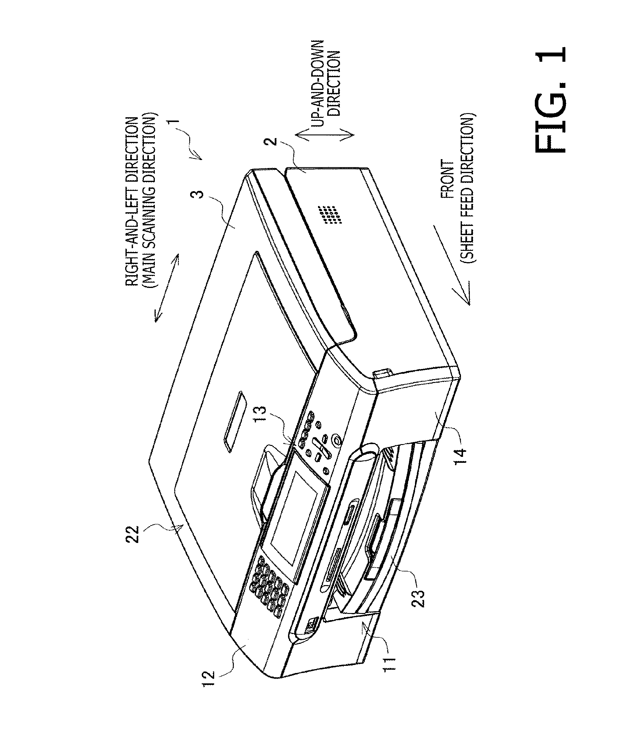
[0042]In FIG. 1, an up-and-down direction, a right-and-left direction and a front-and-rear direction are defined when the inkjet printer 1 is placed for use.

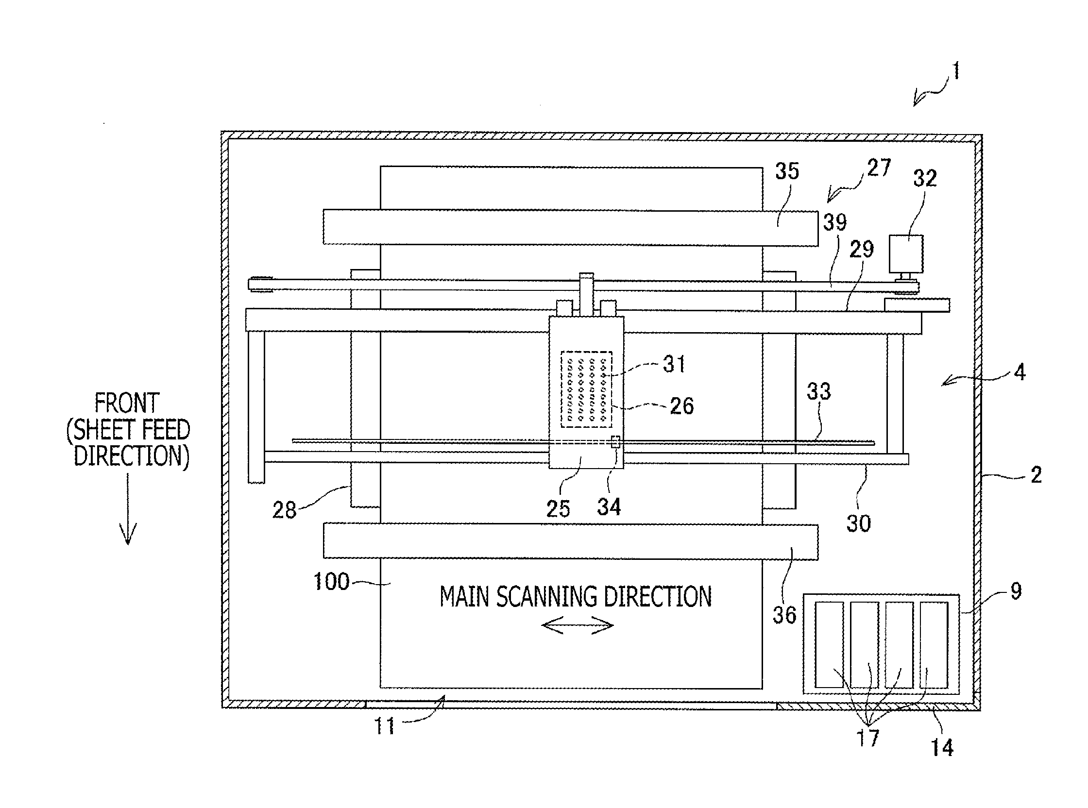
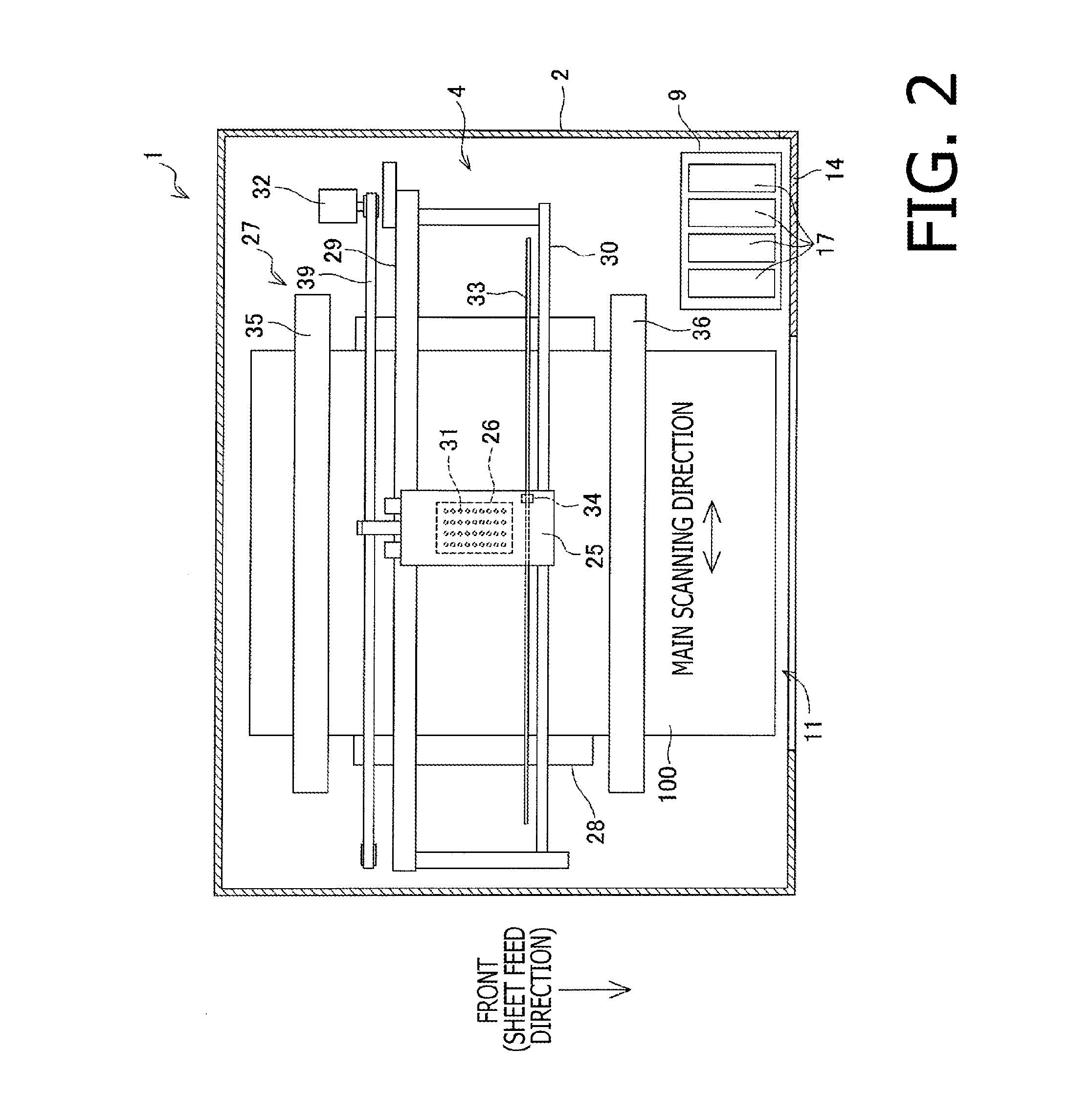
[0043]The inkjet printer 1 has a housing 2, a cover 3 which is rotatably attached to the housing 2. As shown in FIG. 2, the housing 4 accommodates a printer unit 4 which prints images on print sheet 100. A sheet discharge part 11 is formed on the housing 2. The sheet discharge part 11 is opened forward and the print sheet 100 on which an image is formed by the printer unit 4 is discharged therefrom. A part of the housing 2, on a front side of the cover 3, is formed with an inclined surface 12. On the inclined surface 12, an operation panel 13 is provided. A portion of the housing 2, on a right side of the discharge part 11, a lid 14 is attached. On a rear side of the lid 14, a holder 9, to w...


PUM


Abstract

An ejection adjustment pattern forming method of forming an ejection adjustment pattern on a print medium with an inkjet head, which has a plurality of nozzles, with moving the inkjet head in a predetermined scanning direction. The method forms a plurality of thickness measurement patterns respectively on a plurality of pattern forming areas defined on the print medium by causing the plurality of nozzles of the inkjet head to eject ink drops, and forms a plurality of judging patterns respectively on the plurality of pattern forming areas. The ejection conditions of the plurality of nozzles, when the plurality of thickness measurement patterns are formed, are the same among the plurality of pattern forming areas. Further, the ejection conditions of the plurality of nozzles when the first judging pattern is formed and when the second judging pattern is formed are the same among the plurality of pattern forming areas.

Description

CROSS-REFERENCE TO RELATED APPLICATION[0001]This application claims priority under 35 U.S.C. §119 from Japanese Patent Applications No. 2012-153715 and No. 2012-153716, both filed on Jul. 9, 2012. The entire subject matter of the application is incorporated herein by reference.BACKGROUND[0002]1. Technical Field[0003]The present invention relates to a technique of adjusting ink ejection of nozzles of an inkjet head. Specifically, the invention relates to the technique of suppressing unevenness of ejection amount of ink due to uneven characteristics of ink ejection among a plurality of nozzles of the inkjet head.[0004]2. Prior Art[0005]Conventionally, in a field of an inkjet printer, it has been known that the unevenness of the thickness is observed on an image formed on a print sheet due to unevenness of the ink ejection characteristics among the nozzles of the inkjet head.[0006]The unevenness of the ink ejection characteristics may include unevenness of resistance in ink flow paths ...

Claims


Application Information

Patent Timeline
IPC IPC(8): B41J2/125B41J2/07
CPCB41J2/125B41J2/07B41J29/393B41J2/2135B41J2/04541B41J2/04543B41J2/04505
Inventor OGAWA, MASANOBU
Owner BROTHER KOGYO KK
Why Eureka
Try Eureka