Dental abutment for oral scanning

a scanning abutment and dental implant technology, applied in the field of dental implants, can solve the problems of providing a rather poor scanning accuracy, affecting the patient's comfort, and causing additional costs and pain for patients, and achieves the effect of improving the fitting of the implant and ensuring the accuracy of the scanning results

Active Publication Date: 2014-01-09
ELOS MEDTECH PINOL AS
View PDF14 Cites 14 Cited by
  • Summary
  • Abstract
  • Description
  • Claims
  • Application Information

AI Technical Summary

Benefits of technology

[0006]Thus, according to the above, it is an object of the present invention to provide a scan body element which is capable of providing more precise scanning results, thus allowing manufacturing of dental products with better fitting to an implant.

Problems solved by technology

However, it appears that this system provides a rather poor precision in the scanning result with respect to the orientation of the implant, as the scan element is mounted on a further part screwed into the implant, thus introducing a possible error in determination of tilt angle of the implant.
Therefore, the resulting dental bridge or bar manufactured based on such scan may suffer from imprecise fitting onto the implant which may cause various health problems, e.g. infections and bone deterioration, thus providing additional costs and pain for the patient.
Furthermore, it can be a rather cumbersome process to fasten each part necessary to do the scan individually on the implant, especially when the scanning is performed inter-orally.

Method used


Image

  • Dental abutment for oral scanning
  • Dental abutment for oral scanning
  • Dental abutment for oral scanning

Examples


embodiment 1

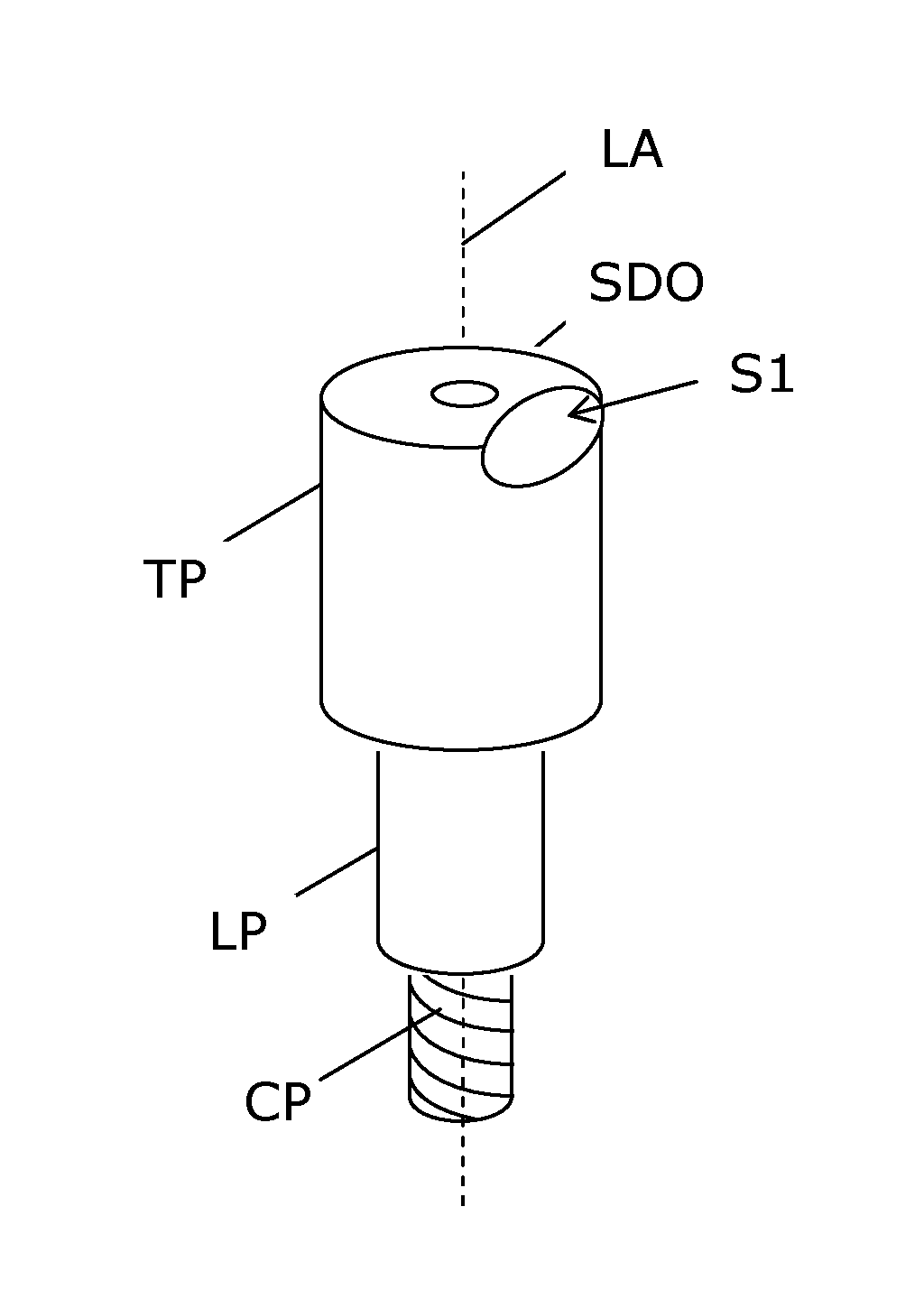
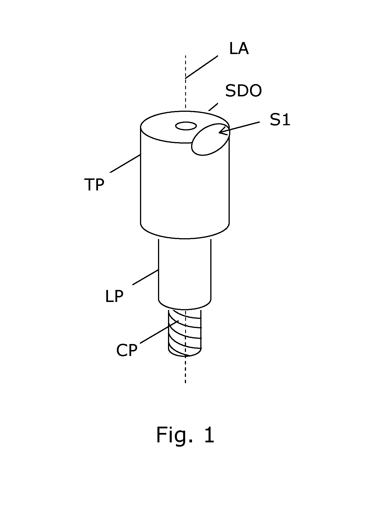
[0061]2. Scan body element , wherein the top part (TP) and the lower part (LP) comprise openings (SDO) arranged for insertion of a screw driver, so as to allow the screw driver to be received in said recess (R) of the central part (CP).

[0062]3. Scan body element according to embodiment 1 or 2, wherein the central part (CP) is displaceable relative to the lower part (LP) along a longitudinal axis (LA).

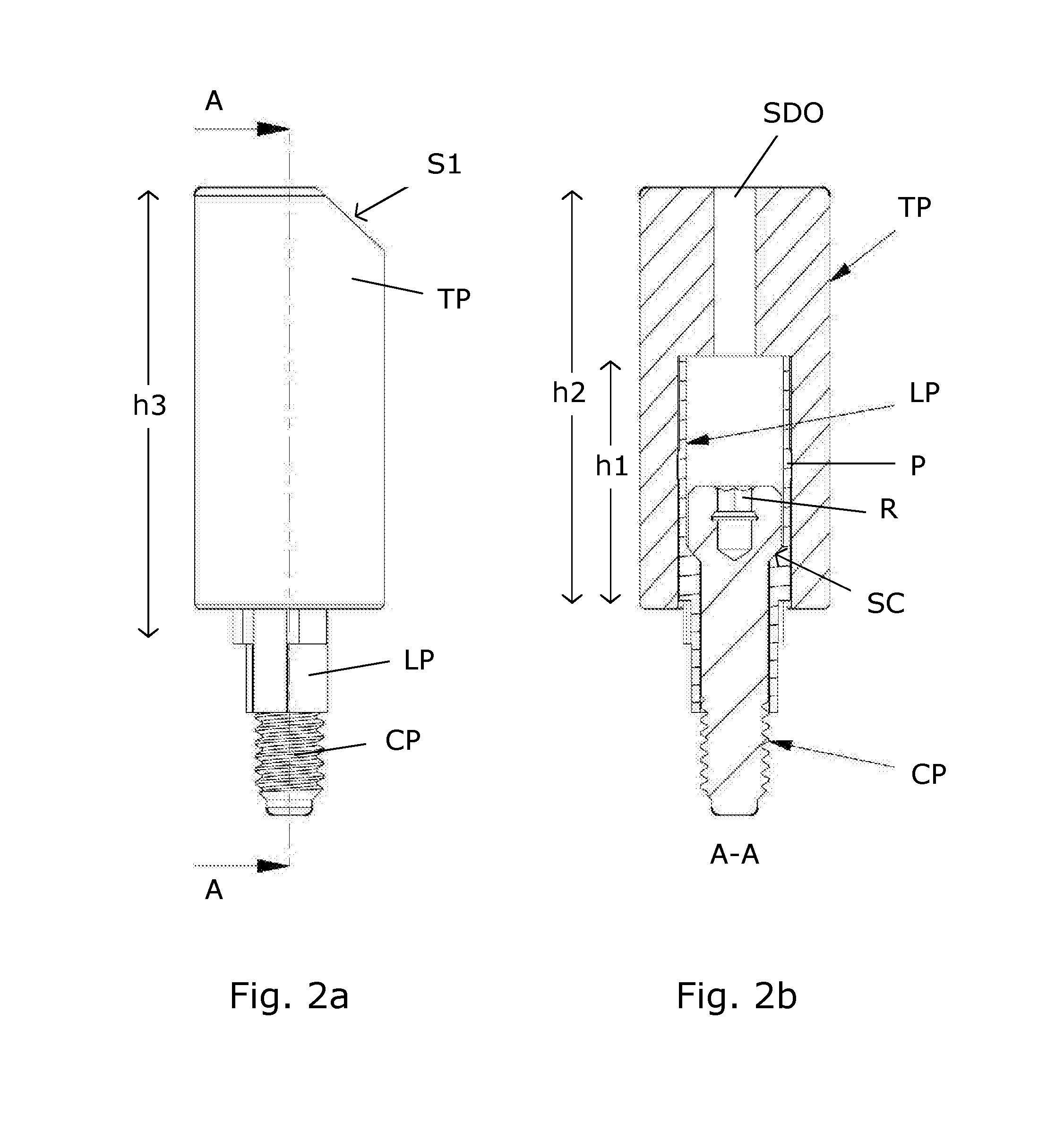
[0063]4. Scan body element according to any of the preceding embodiment, wherein the top part (TP) is locked in position relative to the lower part (LP) by means of at least one of:[0064]one or more exterior protrusions (P) on the lower part (LP) arranged for being press fitted inside the top part (TP),[0065]by means of glue,[0066]by means of co-moulding,[0067]by means of corresponding threads on the top part (TP) and the lower part (LP), and[0068]by means of a shrinking process.

[0069]5. Scan body element according to any of the preceding embodiment, wherein the top part (TP) is a solid...

embodiment 8

[0073]9. Scan body element , wherein a length (h1) of the upper portion of the lower part (LP) being surrounded by the top part (TP) is at least 20% of an outer height (h2) of the top part (TP), such as at least 30%, such as at least 40%, such as at least 50%, such as at least 60%, such as at least 70%, such as at least 80%, such as at least 90%.

[0074]10. Scan body element according to any of the preceding embodiments, wherein a total outer height (h3) of the scan body element above the implant or implant analog is below 15 mm, when the scan body element is mounted on the implant or implant analog.

[0075]11. Scan body element according to any of the preceding embodiment, wherein the lower part (LP) surrounds an upper portion of the central part (CP).

[0076]12. Scan body element according to any of the preceding embodiment, wherein an inner surface of the lower part (LP) and an outer surface of the upper portion of the central part (CP) are shaped such that the central part (CP) provid...


PUM


Abstract

A scan body element to be inserted in a dental implant or implant analog for scanning with, or in, an optical scanning system. The scan body element has a polymer or a ceramic top part (TP) with at least one geometric feature (S1) recognizable in the scanning. A metallic lower part (LP) is shaped to fit to a dental implant or an analog, and fixed to the top part (TP), e.g. by press fitting. A central part (CP) is arranged inside the lower part (LP), and comprises a threaded portion, and a recess (R) for receiving a screw driver through a hole in the top part (SDO), thus allowing the threaded portion to be turned relative to the lower part (LP) to fasten the scan body element to the implant or the analog. The central part (CP) may be interlocked between the lower part (LP) and the top part (TP) and thus the scan body element constitutes one single element for normal use.

Description

FIELD OF THE INVENTION[0001]The invention relates to the field of devices for implantation. More specifically, the invention provides a scan body element or scanning abutment for dental implants which is suited for high precision inter-oral scanning while mounted on a dental implant. However, the scan body element is also suited for extra-oral scanning when mounted on an implant analog, e.g. mounted in a mould of the patient's mouth.BACKGROUND OF THE INVENTION[0002]Custom made dental abutments, such as crowns or bridges for mounting on an implant fastened in the jaw bone of a patient, are commonly manufactured based on a scanning. A scanning is performed of a scan body element or scanning abutment mounted on an implant analog in a mould of the patient's mouth, i.e. outside the patient's mouth. Alternatively, the scanning can be performed in the mouth of the patient with the scan body element mounted on an implant which has been implanted in the jaw bone of the patient, i.e. inter-or...

Claims


Application Information

Patent Timeline
Patent Type & Authority Applications(United States)
IPC IPC(8): A61B5/00A61C8/00
CPCA61B5/0088A61C8/00A61B5/0062A61B5/4547A61B2090/3937A61C8/0001A61C9/004
Inventor THOMSEN, CHRISTIAN SCHARFE
Owner ELOS MEDTECH PINOL AS
Why Eureka
Try Eureka