Autonomous vacuum cleaner

a vacuum cleaner and autonomous technology, applied in the field of autonomous vacuum cleaners, can solve the problems of affecting the cleaning efficiency of the machine over time, and the cleaning performance tends to be less than satisfactory, so as to improve the cleaning efficiency of the appliance, reduce the pressure drop in the region, and increase the dust capacity without increasing the height of the vacuum cleaner.

Inactive Publication Date: 2014-01-16
DYSON TECH LTD
View PDF0 Cites 36 Cited by
  • Summary
  • Abstract
  • Description
  • Claims
  • Application Information

AI Technical Summary

Benefits of technology

[0006]By providing a robotic vacuum cleaner with a cyclonic separating apparatus having two stages of cyclones, a first upstream cyclone and a plurality of downsteam parallel cyclones, the cleaning efficiency of the appliance is improved significantly compared with known robotic cleaners. Therefore, the performance of the robotic vacuum cleaner of the invention is comparable or potentially exceeds that of the more common manually operated cylinder or upright machines.
[0007]In one embodiment, the cyclonic separating apparatus is supported on the chassis so that the longitudinal axis of the separating apparatus is oriented substantially parallel to the chassis. This horizontal orientation of the separating apparatus permits the separating apparatus to be lengthened, therefore increasing its dust capacity without increasing the height of the vacuum cleaner. In such an arrangement, the inlet to the separating apparatus is positioned directly above an outlet of the cleaner head which enables a substantially straight flow path between the cleaner head and the inlet of the cyclonic separating apparatus. This configuration helps to minimize the pressure drop in the region between the cleaner head and the separating apparatus.
[0008]In an alternative embodiment, the cyclonic separating apparatus is supported on the chassis with the longitudinal axis of the separating apparatus oriented substantially perpendicular to the chassis. This arrangement enables the vertical height of the separating apparatus to be configured so that it does not extend beyond the upper surface of the vacuum cleaner.
[0009]To ensure the cyclonic separator is compact, the plurality of second cyclones may be arranged radially around a longitudinal axis of the first cyclone, and within the first cyclone. Furthermore, the first cyclone may be substantially cylindrical in shape, primarily due to the shape of the outer housing of the cyclone separating apparatus, and the plurality of downstream cyclones may be frustoconical in shape so as to promote a high speed airflow thereby increasing separating efficiency, particularly of small particles.

Problems solved by technology

The drawback with these arrangements is that as the bag, or container, fills up with debris it will become clogged so that the cleaning performance of the machine will suffer over time.
More generally, cleaning performance tends to be less than satisfactory since the focus is on providing the vacuum cleaner with a sophisticated autonomous control system and a rather basic floor cleaning scheme to sweep dirt and dust from the floor rather than providing a powerful suction action as is found on upright type vacuum cleaners, for example.

Method used


Image

  • Autonomous vacuum cleaner
  • Autonomous vacuum cleaner
  • Autonomous vacuum cleaner

Examples


Embodiment Construction

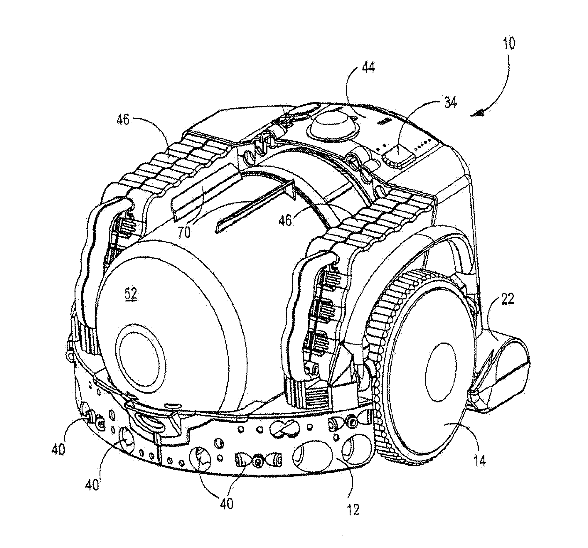
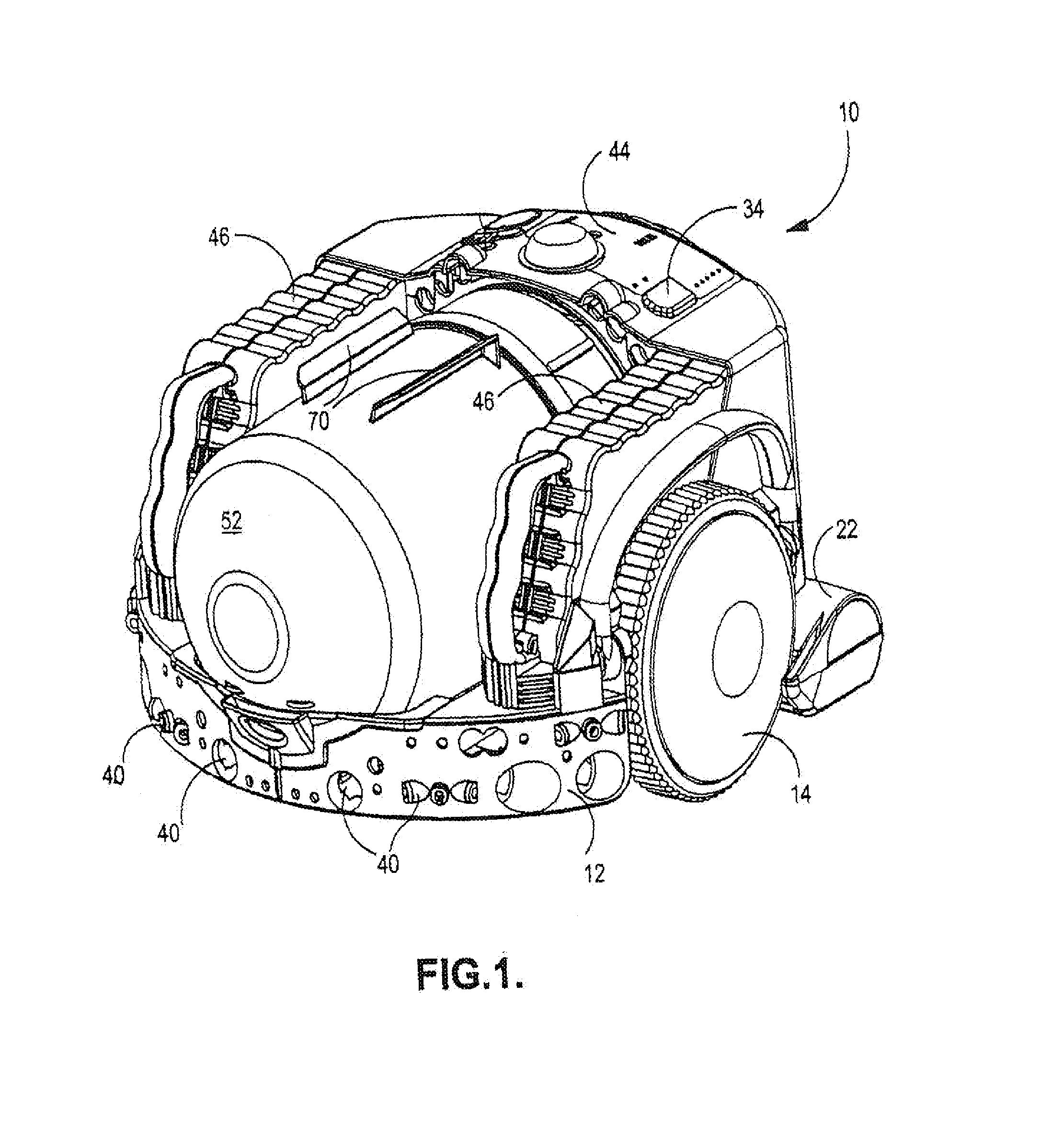
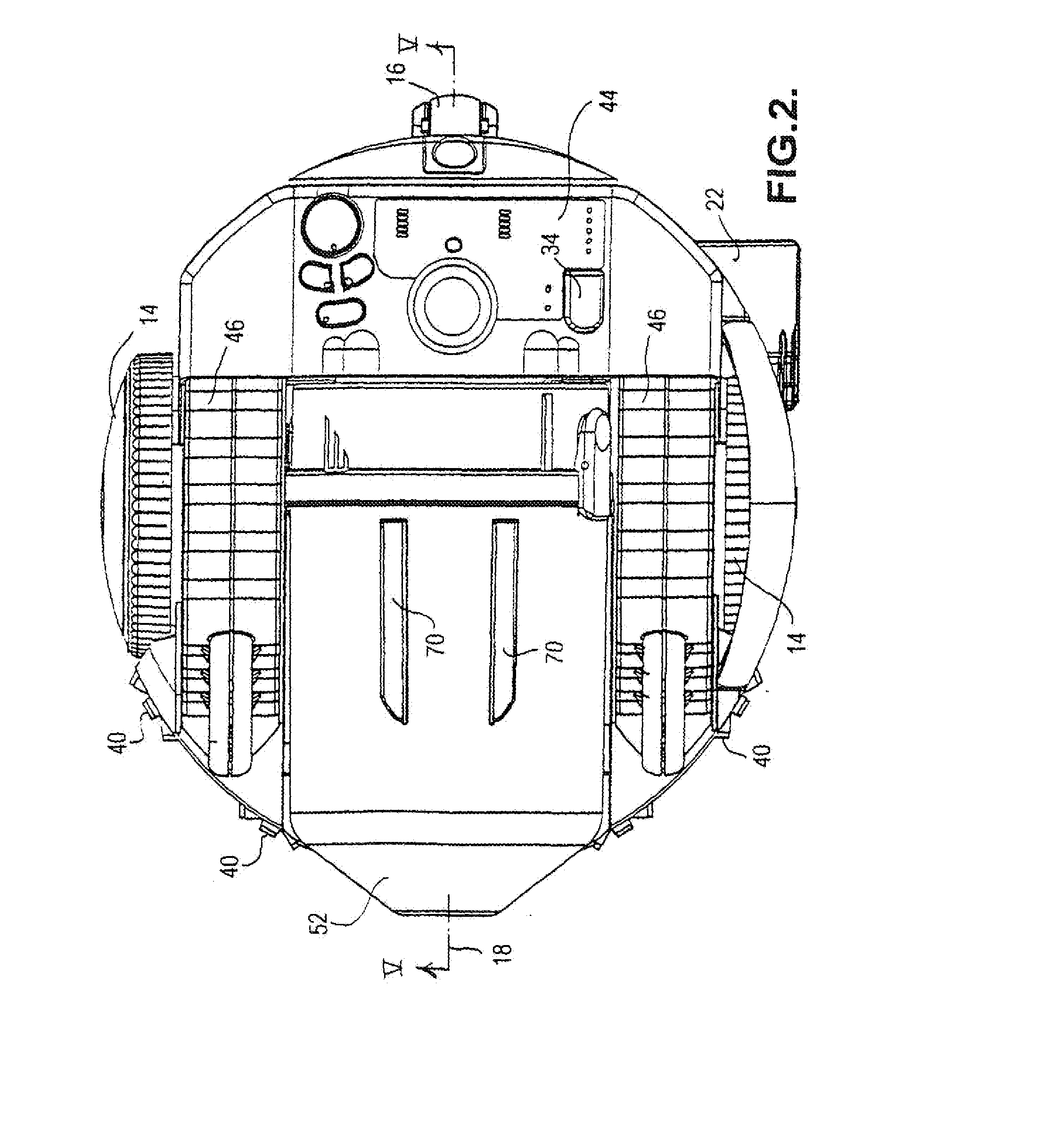
[0018]Referring firstly to FIGS. 1 to 5, a vacuum cleaner 10 has a supporting chassis 12 which is generally circular in shape and is supported on two driven traction wheels 14 and a castor wheel 16. The chassis 12 is preferably manufactured from high-strength moulded plastics material, such as ABS, but can equally be made from metal such as aluminium or steel. The chassis 12 provides support for the components of the vacuum cleaner 10 which will be described in more detail below.

[0019]The driven wheels 14 are arranged diametrically opposed at either side of the chassis 12, and therefore share an axis that is perpendicular to the longitudinal axis of the vacuum cleaner 10 which, it should be noted, is oriented along the direction of travel of the vacuum cleaner 10. Each driven wheel 14 is moulded from a high-strength plastics material and carries a comparatively soft, ridged band around its circumference to enhance the grip of the wheel when the vacuum cleaner 10 is traversing a smoo...


PUM


Abstract

An autonomous vacuum cleaner comprising a chassis, a traction part for supporting the vacuum cleaner on a surface, a driving part for driving the traction part and a control system configured to control the driving part to guide the vacuum cleaner across a surface to be cleaned. The vacuum cleaner further includes a cleaner head having a dirty air inlet facing the surface to be cleaned and a separating apparatus carried by the chassis and communicating with the cleaner head in order to separate debris from an airflow entering the separating apparatus via the dirty air inlet. The separating apparatus comprises a first upstream cyclone and a plurality of second cyclones arranged in parallel with one another and located downstream of the first cyclone.

Description

REFERENCE TO RELATED APPLICATIONS[0001]This application is a national stage application under 35 USC 371 of International Application No. PCT / GB2012 / 050065, filed Jan. 13, 2012, which claims the priority of United Kingdom Application No. 1101940.3, filed Feb. 4, 2011, the entire contents of which are incorporated herein by reference.FIELD OF THE INVENTION[0002]This invention relates to an autonomous vacuum cleaner, also known generally in the art as ‘robotic’ vacuum cleaners.BACKGROUND OF THE INVENTION[0003]Robotic vacuum cleaners, in general, are known and represent a relatively recent but rapidly advancing field of floor cleaning technology. The main advantage of robot vacuum cleaners over manually operated vacuum cleaners is that a robot vacuum cleaner has the facility to guide itself around an area to be cleaned, be it an entire floor of a property or a single room, and so is capable of operating completely or at least largely autonomously and free from human involvement.[0004]S...

Claims


Application Information

Patent Timeline
Patent Type & Authority Applications(United States)
IPC IPC(8): A47L9/16
CPCA47L9/1625A47L9/1633A47L9/1641A47L2201/04A47L2201/00A47L5/22A47L9/009A47L9/16B04C5/185A47L9/00A47L9/28
Inventor DYSON, JAMESGAMMACK, PETER DAVID
Owner DYSON TECH LTD
Why Eureka
Try Eureka