GNSS Signal Processing with Ionospheric Bridging for Reconvergence

a signal processing and ionospheric bridge technology, applied in satellite radio beaconing, measurement devices, instruments, etc., can solve the problems of iono-free code inherently noisy, auxiliary code-carrier filter ambiguity estimates are also noisy, and the geometry filter is distorted into the future. to achieve the effect of reducing convergence/reconvergence times

Active Publication Date: 2014-01-16
TRIMBLE INC
View PDF11 Cites 72 Cited by
  • Summary
  • Abstract
  • Description
  • Claims
  • Application Information

AI Technical Summary

Benefits of technology

[0016]The following invention presents a way of reducing convergence / reconvergence times by taking advantage of:

Problems solved by technology

The method and apparatus described focuses on single reference (base) RTK positioning and does not address the estimation process needed for GVRS positioning.
The disadvantage of position seeding is that if the input coordinates are incorrect, this will corrupt the Geometry filter into the future, unless the filter is reset.
Iono-free code is inherently noisy and therefore the iono-free ambiguity estimates of the Auxiliary Code-Carrier filters are also noisy and only contribute a small amount of information to the float solution.
The low accuracy of the Auxiliary Code-Carrier Filter ambiguity results normally means that they don't contribute significantly to the final FAMCAR combined float solution.
Ionospheric bias is a significant error source for GVRS processing.
The disadvantage of this approach is that the Code-Carrier Filters nominally use the wide-lane carrier phase combination, which contains an ionospheric bias.
Second, the code-carrier filter results contribute significantly to the FAMCAR combined float solution therefore this information would be compromised if replaced by the known position input.

Method used


Image

  • GNSS Signal Processing with Ionospheric Bridging for Reconvergence
  • GNSS Signal Processing with Ionospheric Bridging for Reconvergence
  • GNSS Signal Processing with Ionospheric Bridging for Reconvergence

Examples


Embodiment Construction

[0036]Global Virtual Reference Station (GVRS) Positioning Principles

[0037]Overview

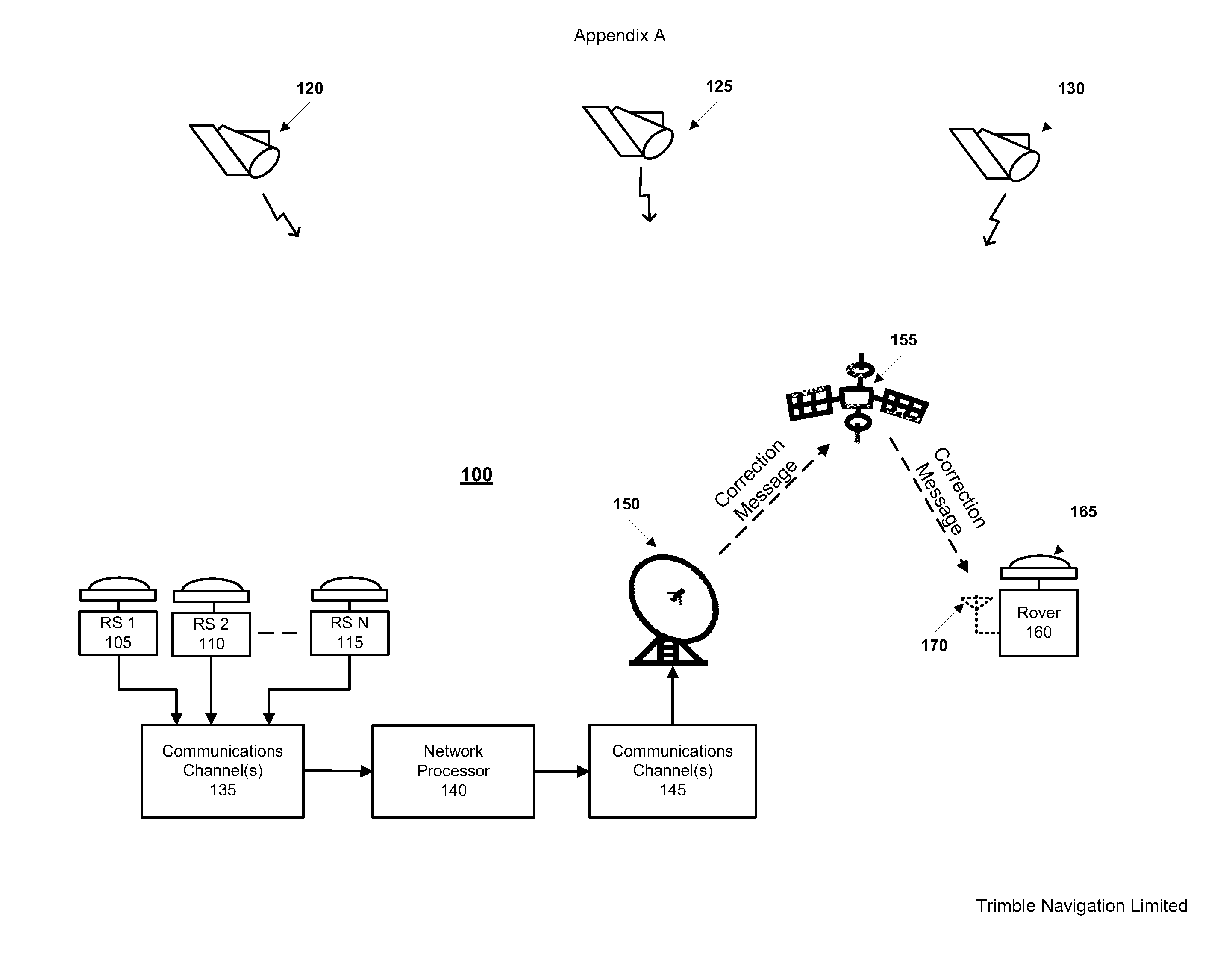
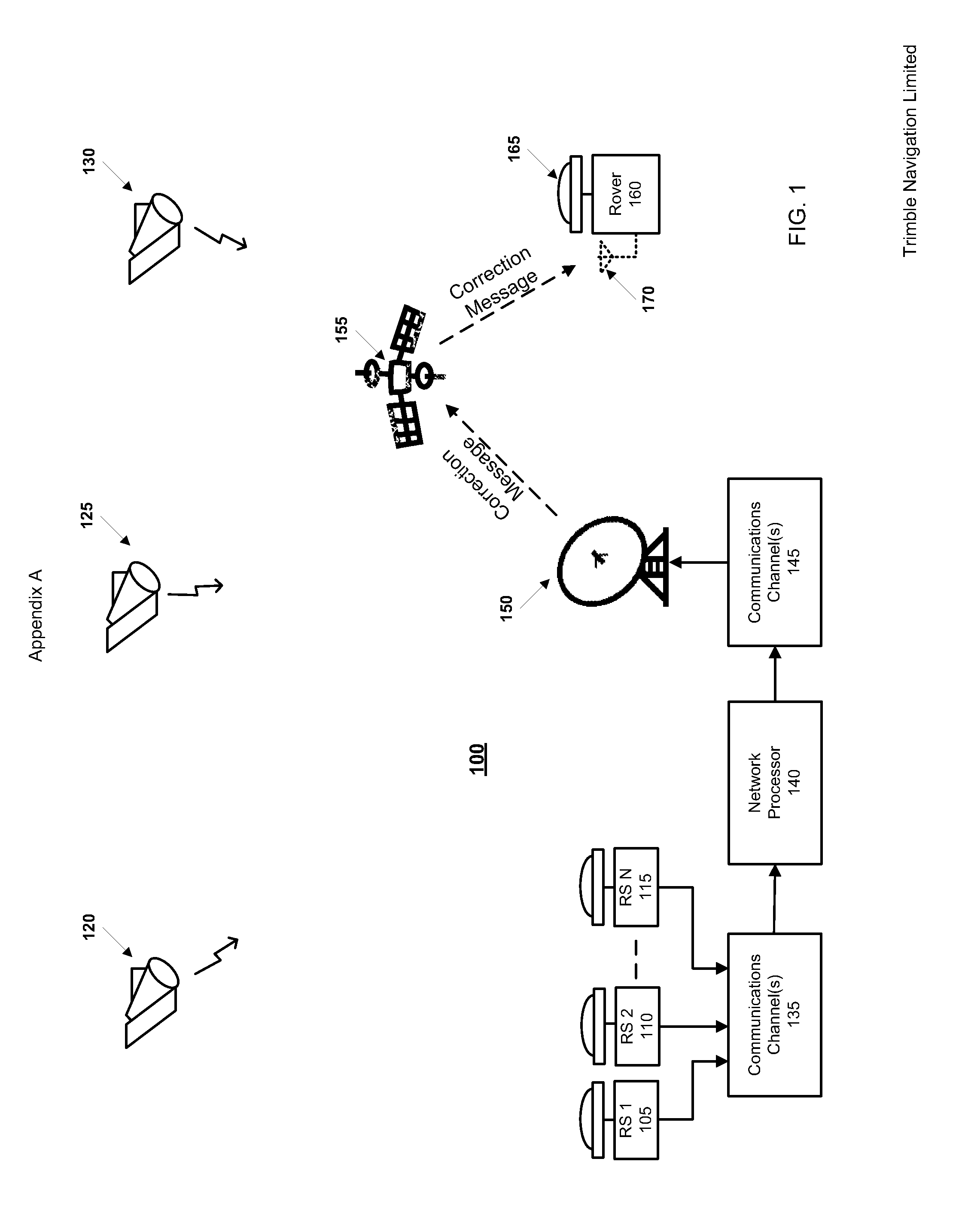
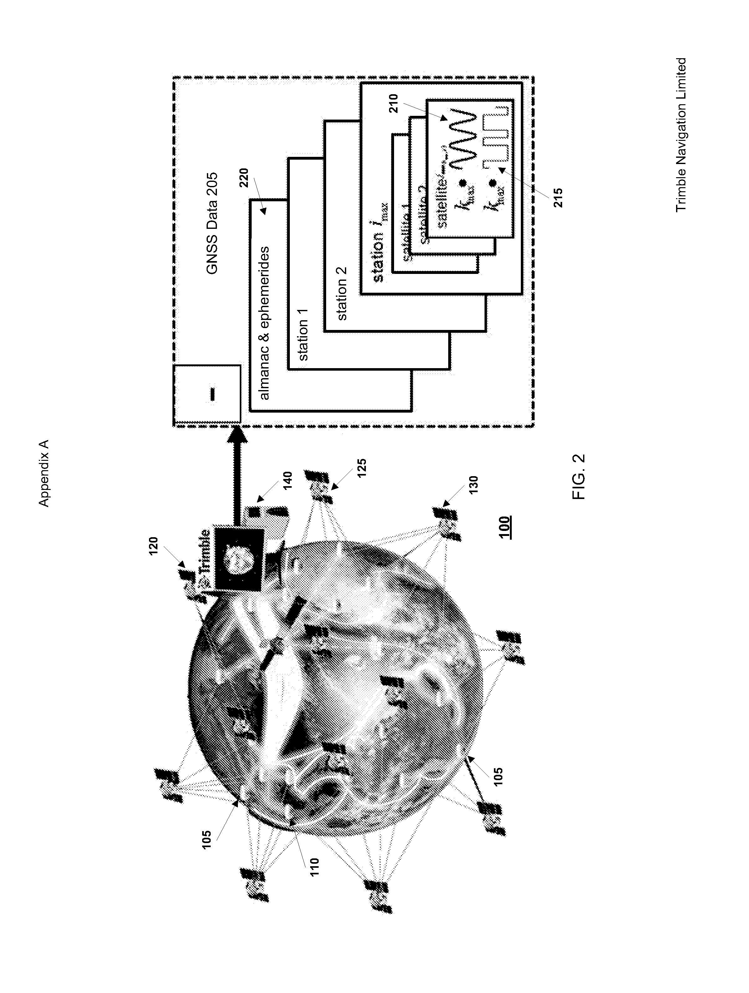
[0038]FIG. 4 shows an embodiment of Global Virtual Reference Station (GVRS) rover processing with GNSS satellite corrections (taken from FIG. 38 of U.S. Provisional Application for Patent No. 61 / 277,184 filed 19 Sep. 2009 (TNL A-2585P)). Rover receiver 3805 receives GNSS signals from multiple GNSS satellites, of which three are shown at 3810, 3815, 3820. Receiver 3805 derives GNSS data 3825 from code observations and carrier-phase observations of the GNSS signals over multiple epochs.

[0039]Precise satellite data 3830 for the GNSS satellites are received, via a correction message broadcast by a communication satellite 3835 in this case, or by other means, such as wireless Internet. The correction messages are decoded by a message decoder 3832. A Synthesized Base Station (SBS) module 3835 receives the precise satellite data 3830 and also receives information which it can use as a virtual base location, s...


PUM


Abstract

Methods and apparatus provide for positioning of a rover antenna from GNSS data derived from multi-frequency signals and correction data derived from a network of reference stations. Rover antenna position and multi-frequency ambiguities are estimated at each epoch. An ionospheric filter models variation in ionospheric bias per satellite. A set of ionospheric carrier-phase ambiguities is estimated at least when the multi-frequency ambiguities have attained a predetermined precision. The estimated ionospheric carrier-phase ambiguities are cached. After detecting interruption of signal at the rover antenna and determining reacquisition of signals at the rover antenna, an ionospheric bias per satellite over an interruption interval is predicted. For each satellite, a cached ionospheric carrier-phase ambiguity is combined with a predicted ionospheric bias to obtain a post-interruption ionospheric ambiguity estimate. The post-interruption ionospheric ambiguity estimates are used to aid estimation of rover antenna position after signal reacquisition.

Description

CROSS REFERENCE TO RELATED APPLICATIONS[0001]The following are related hereto and incorporated herein in their entirety by this reference: U.S. Provisional Application for Patent No. 61 / 277,184 filed 19 Sep. 2009 (TNL A-2585P); International Patent Application PCT / US2010 / 02565 filed 19 Sep. 2010 (TNL A-2565PCT); International Patent Application PCT / US2010 / 02564 filed 19 Sep. 2010 (TNL A-2585PCT); International Patent Application PCT / US2010 / 02563 filed 19 Sep. 2010 (TNL A-2599PCT); International Patent Application PCT / US2010 / 02562 filed 19 Sep. 2010 (TNL A-2617PCT); International Patent Application PCT / US2010 / 02581 filed 19 Sep. 2010 (TNL A-2647PCT); U.S. Provisional Application for Patent No. 61 / 337,980 filed 14 Feb. 2010 (TNL A-2633P); International Patent Application PCT / US2011 / 24733 filed 14 Feb. 2011 (TNL A-2633PCT); International Patent Application PCT / US2011 / 24743 filed 14 Feb. 2011 (TNL A-2939PCT); International Patent Application PCT / US2011 / 24763 filed 14 Feb. 2011 (TNL A-29...

Claims


Application Information

Patent Timeline
Patent Type & Authority Applications(United States)
IPC IPC(8): G01S19/44
CPCG01S19/44G01S19/072G01S19/07G01S19/32G01S19/04G01S19/09G01S19/43
Inventor LEANDRO, RODRIGOVOLLATH, ULRICHTALBOT, NICHOLAS CHARLES
Owner TRIMBLE INC
Why Eureka
Try Eureka