Printer configured for efficient air bubble removal

a printing machine and air bubble technology, applied in printing and other directions, can solve the problems of air bubbles being particularly problematic, increase the risk of ink drooling, and ink drooling is highly undesirable, and minimize ink drooling.

Inactive Publication Date: 2014-01-16
MEMJET TECH LTD
View PDF24 Cites 16 Cited by
  • Summary
  • Abstract
  • Description
  • Claims
  • Application Information

AI Technical Summary

Benefits of technology

[0024]Positioning the first valve below the height of the printhead advantageously maintains a negative ink pressure at printhead nozzles when the first valve is opened to atmosphere. Therefore, this arrangement minimizes ink drooling from the nozzles when the first valve is open. (Ink is unable to drain into the air conduit from the printhead by virtue of the surface tension of menisci in the printhead nozzles).
[0025]By contrast, if the first valve were to be positioned above the height of the printhead, a positive ink pressure is experienced at the printhead nozzles when the first valve is opened, thereby increasing the risk of ink drooling from the nozzles. Ink drooling is highly undesirable during printhead replacement, because users have increased risk of ink staining skin, clothing etc.

Problems solved by technology

Air bubbles are particularly problematic in the second conduit when the ink container is positioned below a height of the printhead.

Method used


Image

  • Printer configured for efficient air bubble removal
  • Printer configured for efficient air bubble removal
  • Printer configured for efficient air bubble removal

Examples


Embodiment Construction

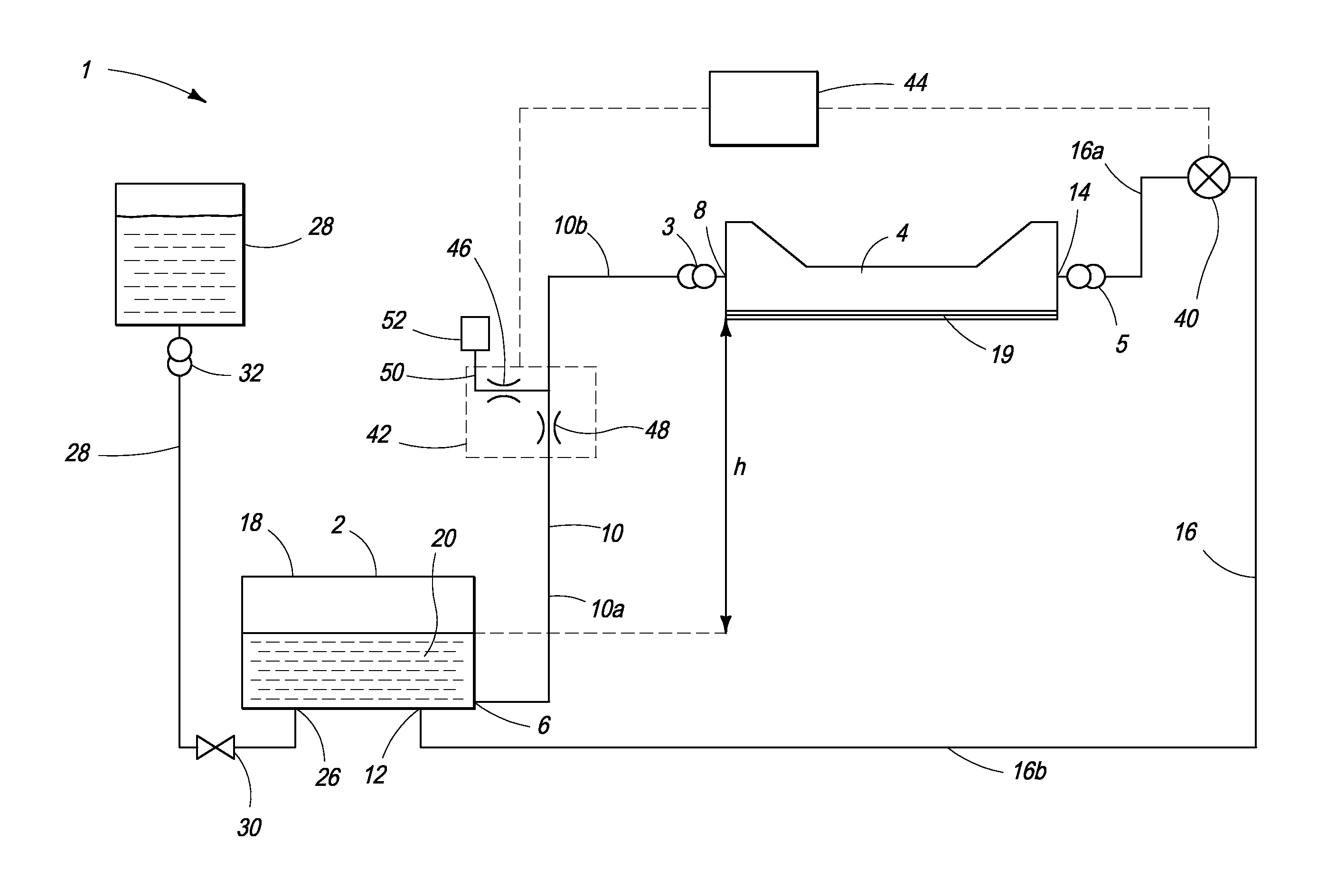
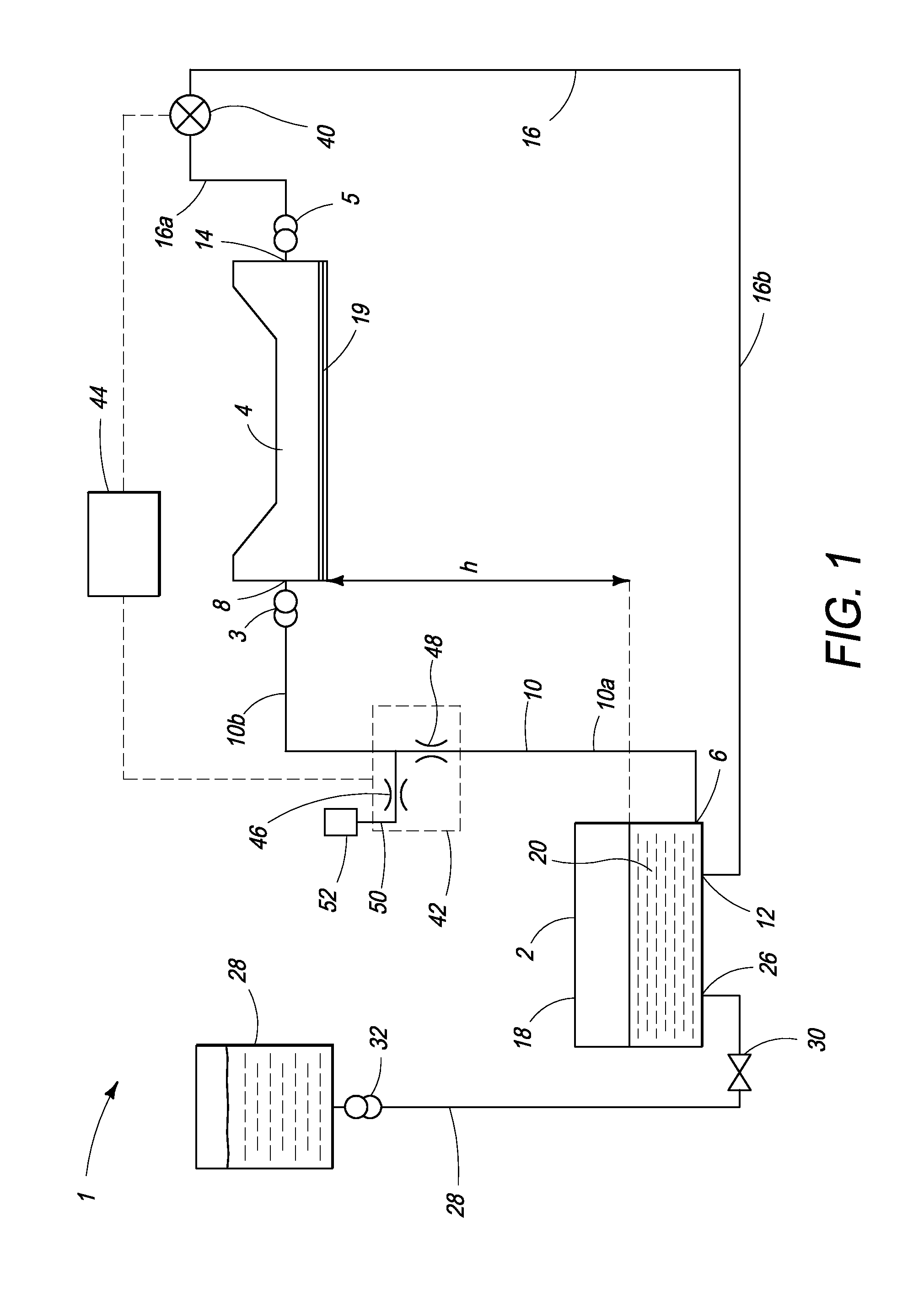
[0051]Referring to FIG. 1, there is shown schematically a printer 1 having an ink delivery system for supplying ink to a printhead. The ink delivery system is similar in function to those described in US2011 / 0279566 and US2011 / 0279562, the contents of which are herein incorporated by reference.

[0052]The printer 1 comprises an ink container 2 having a supply port 6 connected to a first port 8 of a printhead 4 via a first ink conduit 10. A return port 12 of the ink container 2 is connected to a second port 14 of the printhead 4 via a second ink conduit 16. Hence, the ink container 2, the first ink conduit 10, the printhead 4 and the second ink conduit 16 define a closed fluidic loop. Typically, the first ink conduit 10 and second ink conduit 16 are comprised of lengths of flexible tubing.

[0053]The printhead 4 is user-replaceable by means of a first coupling 3 releasably interconnecting the first port 8 and the first ink conduit 10; and a second coupling 5 releasably interconnecting th...


PUM


Abstract

An inkjet printer includes: a printhead having a first port and a second port; an ink container for supplying ink to the printhead, the ink container comprising a supply port and a return port; a first ink conduit interconnecting the supply port and the first port; a second ink conduit interconnecting the return port and the second port; and a pump configured for pumping ink from the supply port to the return port. The second ink conduit has a smaller internal cross-sectional area than the first ink conduit for providing a faster flow speed of ink in the second ink conduit relative to the first ink conduit when the pump is actuated.

Description

FIELD OF THE INVENTION[0001]This invention relates to an ink delivery system for an inkjet printer. It has been developed primarily for flushing air bubbles from a printhead.BACKGROUND OF THE INVENTION[0002]Inkjet printers employing Memjet® technology are commercially available for a number of different printing formats, including home-and-office (“SOHO”) printers, label printers and wideformat printers. Memjet® printers typically comprise one or more stationary inkjet printheads, which are user-replaceable. For example, a SOHO printer comprises a single user-replaceable multi-colored printhead, a high-speed label printer comprises a plurality of user-replaceable monochrome printheads aligned along a media feed direction, and a wideformat printer comprises a plurality of user-replaceable multi-colored printheads in a staggered overlapping arrangement so as to span across a wideformat pagewidth.[0003]Providing users with the ability to replace printheads is key advantage of the Memje...

Claims


Application Information

Patent Timeline
Patent Type & Authority Applications(United States)
IPC IPC(8): B41J2/18
CPCB41J2/18B41J2/175B41J2/19
Inventor ESDAILE-WATTS, EDWARDALEMANA, GILBERTBRICE, ROBERTSANAEI, KIANOUSH MIR
Owner MEMJET TECH LTD
Why Eureka
Try Eureka