Delivery server, and terminal device

Active Publication Date: 2014-01-16
MITSUBISHI ELECTRIC CORP
View PDF9 Cites 0 Cited by
  • Summary
  • Abstract
  • Description
  • Claims
  • Application Information

AI Technical Summary

Benefits of technology

[0008]The present invention was made in view of the above facts, and an object thereof is to provide a conten

Problems solved by technology

Hence, there is the problem that even without overhead such as a re-connection process due to radio communication disconnection at all, it takes a long delivery time to deliver a large amount of conten

Method used


Image

  • Delivery server, and terminal device
  • Delivery server, and terminal device
  • Delivery server, and terminal device

Examples


Example

Embodiment 1

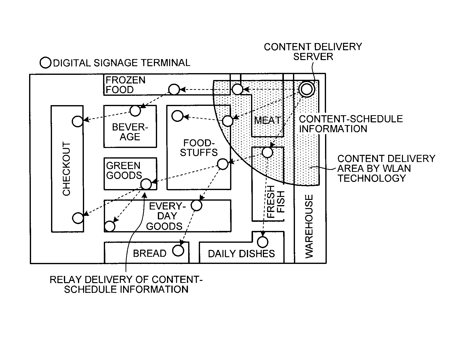
[0021]First, a digital signage system which is a combination of conventional WLAN technology with multi-hop communication technology will be described briefly. FIG. 1 is a diagram showing a digital signage system which is a combination of WLAN technology with multi-hop communication technology. FIG. 1 is an image where digital signage terminals are installed in sales space in a retail store to perform advertisement, and shows that where digital signage terminals use WLAN technology, wherein terminals directly connect to an access point (a content delivery server in FIG. 1), digital signage terminals need to be installed within a fan-shaped range. By combining with multi-hop communication technology, installation in places where direct connection cannot be made is enabled, and merits such as communication continuation due to path redundancy or the like can be enjoyed. By using this connection configuration to deliver content and schedule to be displayed to each digital si...

Example

Embodiment 2

[0046]In this embodiment, a server and terminals perform multicasting delivery. The differences from Embodiment 1 will be described.

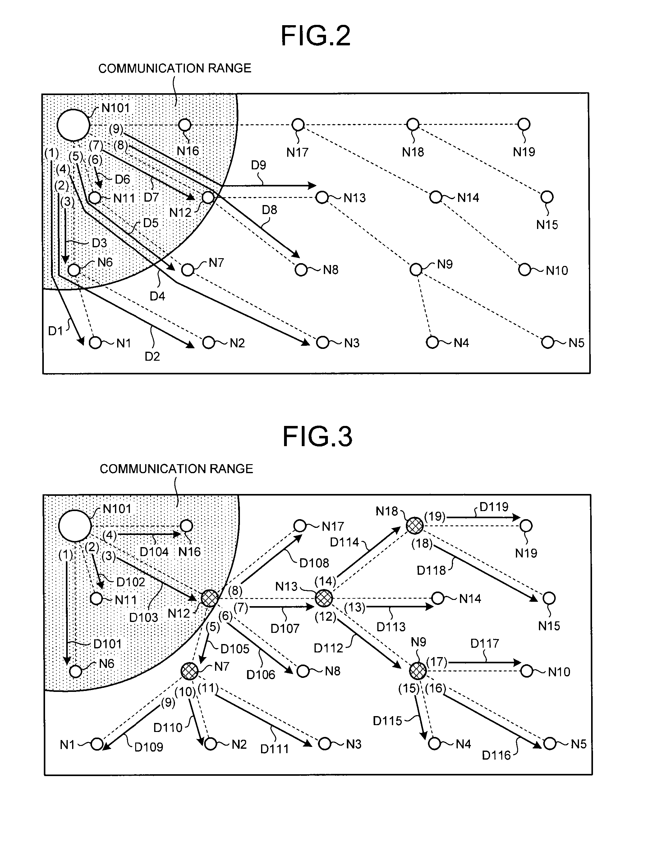
[0047]FIG. 7 is a diagram showing communication paths in the content delivery system according to the present embodiment. A server N101 and terminals N1 to N19 have a transmit-receive function for multicasting communication. The type of multicasting communication may be communication simply using multicast addresses or communication wherein error correction by which the reception side can correct a frame error from multiple frames is carried out.

[0048]In the present embodiment, the server N101 and terminals N1 to N19 use multicasting delivery for a range where they can simultaneously transmit and receive by radio communication. At the time of multicasting delivery, the server N101 and terminals N1 to N19 set communication speed to match a terminal whose environment is the worst in order to select a common communication speed, and combine an ...

Example

Embodiment 3

[0065]In this embodiment, multiple terminals perform delivery processes at the same time. The differences from Embodiments 1, 2 will be described.

[0066]In Embodiments 1, 2, the server N101 manages terminals which perform delivery by radio communication such that one terminal delivers at a time, thus preventing interference by radio. However, if the space is known beforehand to be broad enough that radio waves do not interfere in the respective areas of, e.g., terminals N7 and N18 in FIG. 3, two or more terminals may perform delivery processes in parallel at the same time.

[0067]The server N101 finds out the amount of interference between the terminals in the network as well as managing network topology according to a routing protocol in advance of information delivery of content and schedule. When calculating the amount of interference, the server N101 may automatically generate a test signal or allow a user to enter manually. Further, the server N101 may perform calculat...


PUM


Abstract

A content delivery system which comprises a delivery server and multiple terminal devices, the delivery server delivering content, the multiple terminal devices receiving delivery of the content, in the content delivery system connection between the delivery server and the terminal devices and connection between the terminal devices being made by radio, in the content delivery system the terminal devices being connected in multiple stages, wherein the delivery server instructs a terminal device which has received delivery of the content and which is connected to an other terminal device at the next stage to deliver content possessed by a self terminal device to the other terminal device, and wherein the instructed terminal device delivers content possessed by the self terminal device to the other terminal device and notifies the delivery result to the delivery server.

Description

BACKGROUND OF THE INVENTION[0001]1. Field of the Invention[0002]The present invention relates to a content delivery system that delivers content.[0003]2. Description of the Related Art[0004]Conventionally, techniques such as signboards, posters, bulletin boards, showcases, and the distribution of handbills or pamphlets have been used as methods of displaying information to the general public. However, where substances such as printed literature or exhibits are involved, it has been difficult to achieve a change to content in a short time. In order to solve this problem, it has been proposed to change signboards, posters, or bulletin boards throughout town for display apparatuses to display according to the advertisement technique used in broadcasting, and in these years a market which is collectively referred to by the term “digital signage” is beginning to be formed. By means of the digital signage, information display can be effectively performed in the form of a product advertise...

Claims


Application Information

Patent Timeline
IPC IPC(8): H04W4/06
CPCH04W4/06
Inventor HIRAI, HIROAKI
Owner MITSUBISHI ELECTRIC CORP
Why Eureka
Try Eureka