Auxiliary device for articulator

a technology of auxiliary devices and articulators, which is applied in the field of auxiliary devices for articulators, can solve the problems of patient stoppage, abnormal growth, and doctor's work with dental casts and separated tooth parts for a long time, and achieves the effects of high degree of freedom, easy fixation through a compressing member, and simple operation

Inactive Publication Date: 2014-01-16
NAT CHENG KUNG UNIV
View PDF5 Cites 4 Cited by
  • Summary
  • Abstract
  • Description
  • Claims
  • Application Information

AI Technical Summary

Benefits of technology

[0028]As mentioned above, the auxiliary device of the invention has at least an adjusting structure and a base, so that the articulator can be steadily fixed on the base and then the dental cast or teeth portions can be adjusted through the movement of the adjusting structure, which has high degrees of freedom. In addition, after adjusting to a desired angle, the adjusting structure can easily fixed through a compressing member. This is very simple in operation and does not need to use wax to fix the teeth portions. Thus, the time for applying and solidifying the wax can be skipped, which allows the operator and doctor to precisely create the operation plan. Furthermore, since the auxiliary device can enhance the stability and convenience of the articulator in operation, the operation of the articulator and the preoperative planning can be properly adjusted immediately.
[0029]Compared with the conventional art, the adjusting structure of the invention is similar to a robot arm, so that the operator or doctor can easily adjusting the adjusting st

Problems solved by technology

Such a kind of abnormally growth problem often accompanies with the facial asymmetry, the mandibular prognathism, the mandible retrusion or the poor occlusal condition on the organization structure.
Regarding the life, the patient tends to encounter the stoppages, such as the pronunciation difficulties, the chewing digestive diseases, the lack of confidence, or even the other's discrimination and the p

Method used


Image

  • Auxiliary device for articulator
  • Auxiliary device for articulator
  • Auxiliary device for articulator

Examples


Embodiment Construction

[0039]The present invention will be apparent from the following detailed description, which proceeds with reference to the accompanying drawings, wherein the same references relate to the same elements.

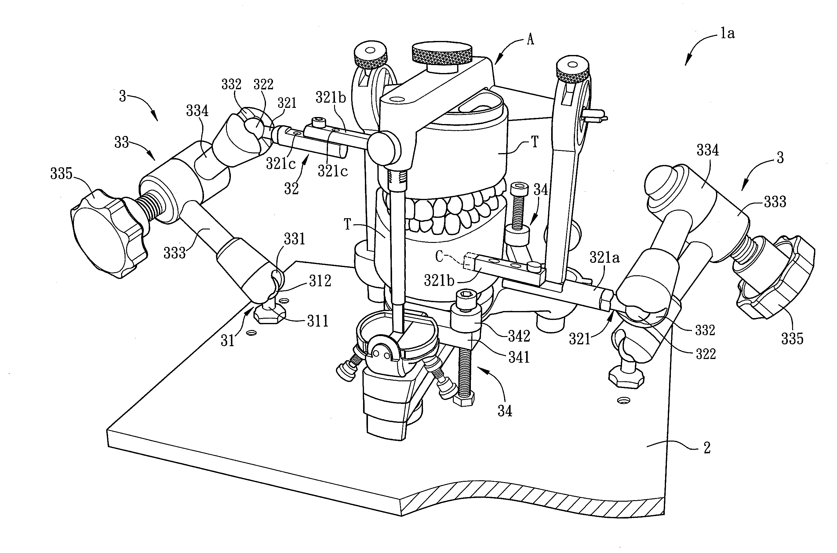
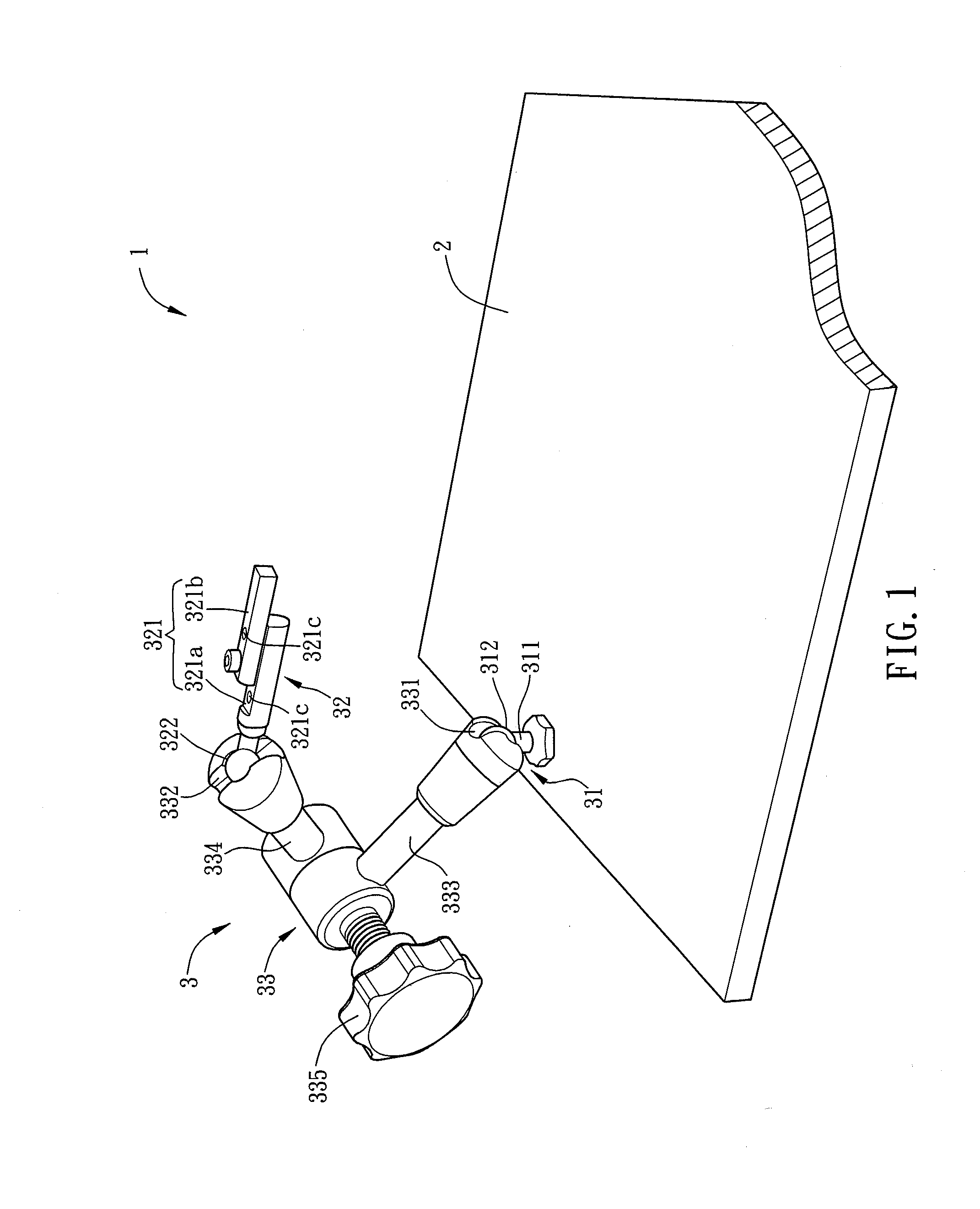
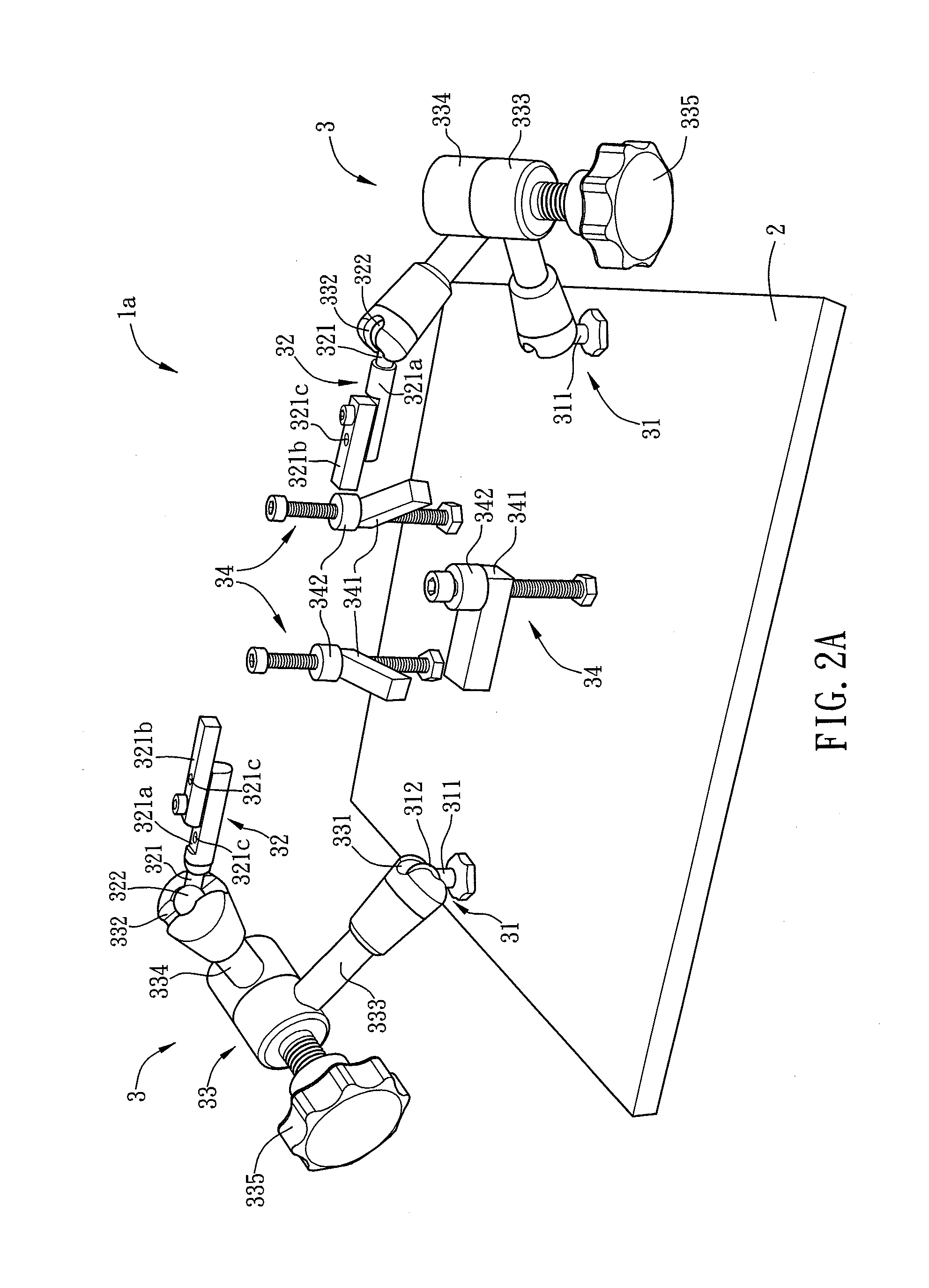
[0040]FIG. 1 is a schematic diagram showing an auxiliary device 1 for an articulator according to a preferred embodiment of the present invention. Referring to FIG. 1, the auxiliary device 1 includes a base 2 and at least an adjusting structure 3. The base 2 is a metal plate for positioning an articulator so as to increase its operating stability. The adjusting structure 3 is detachably disposed on the base 2. For example, the adjusting structure 3 is disposed on the base 2 by way of screwing or locking, so that the adjusting structure 3 can be detached from the base 2. The structure feature and elements of the adjusting structure 3 will be described hereinafter.

[0041]As shown in FIG. 1, the adjusting structure 3 includes a first ball joint 31, a second ball joint 32, and a connecting...


PUM


Abstract

An auxiliary device for an articulator includes a base and at least an adjusting structure. The base is provided for positioning an articulator, and the adjusting structure is disposed on the base. The adjusting structure includes a first ball joint, a second ball joint and a connecting assembly. The first ball joint is connected to the base, and the two ends of the connecting assembly are connected to the first ball joint and the second ball joint, respectively. The adjusting structure is moved relatively to the articulator by the movement of at least one of the first ball joint and the second ball joint, thereby adjusting the position of a dental cast disposed on the articulator. The auxiliary device is advantageous for conveniently adjusting the dental cast disposed on the articulator and accelerating the process of the preoperative planning.

Description

CROSS REFERENCE TO RELATED APPLICATIONS[0001]This Non-provisional application claims priority under 35 U.S.C. §119(a) on Patent Application No(s). 101124920 filed in Taiwan, Republic of China on Jul. 11, 2012, the entire contents of which are hereby incorporated by reference.BACKGROUND OF THE INVENTION[0002]1. Field of Invention[0003]The present invention relates to an auxiliary device and, in particular, to an auxiliary device for an articulator.[0004]2. Related Art[0005]Clinically, there are many patients having special maxillofacial ratios or incorrect occlusal relationships between upper and lower rows of teeth. Such a kind of abnormally growth problem often accompanies with the facial asymmetry, the mandibular prognathism, the mandible retrusion or the poor occlusal condition on the organization structure. Regarding the life, the patient tends to encounter the stoppages, such as the pronunciation difficulties, the chewing digestive diseases, the lack of confidence, or even the ...

Claims


Application Information

Patent Timeline
IPC IPC(8): A61C11/00
CPCA61C11/00A61C11/084
Inventor FANG, JING-JINGWONG, TUNG-YIUWU, TUNG-CHINKUO, TAI-HONGTSENG, CHUN-JU
Owner NAT CHENG KUNG UNIV
Why Eureka
Try Eureka