
Method For Applying A Surgical Clip Having A Compliant Portion

a technology of surgical clips and compliant parts, applied in the field of surgical clips, can solve the problems of excessive blood loss and/or unnecessary damage to the vessel, difficult preloading of known ligation clips into clip appliers, and excessive leg separation of clips, etc., to achieve easy tissue movement, less plastic deformation, and some elasticity

Inactive Publication Date: 2014-01-16
CILAG GMBH INT +1
View PDF26 Cites 1061 Cited by
  • Summary
  • Abstract
  • Description
  • Claims
  • Application Information

AI Technical Summary

Benefits of technology

The invention relates to a ligation clip for use in surgical procedures, which has raised areas on its inner or outer surface to reduce plastic deformation and maintain elasticity when the clip is closed. The clip also has a compliant portion on its inner surface that can improve effectiveness, compensate for larger openings, and make the clip less sensitive to form. This design allows the clip to apply a consistent and reliable pressure on the tissue, even after the closing force has been removed.

Problems solved by technology

One drawback associated with some current clips used for ligating vessels is that the legs of the clip may tend to separate to some extent following release from a clip applier.
Duck-billing can result in insufficient ligation of a vessel, thus leading to excessive blood loss and / or unnecessary damage to the vessel.
Further, some known ligation clips are often difficult to preload into a clip applier because of resistance between the tissue disposed between the jaws and the gripping features on the clip legs.

Method used


Image

  • Method For Applying A Surgical Clip Having A Compliant Portion
  • Method For Applying A Surgical Clip Having A Compliant Portion
  • Method For Applying A Surgical Clip Having A Compliant Portion

Examples


Embodiment Construction

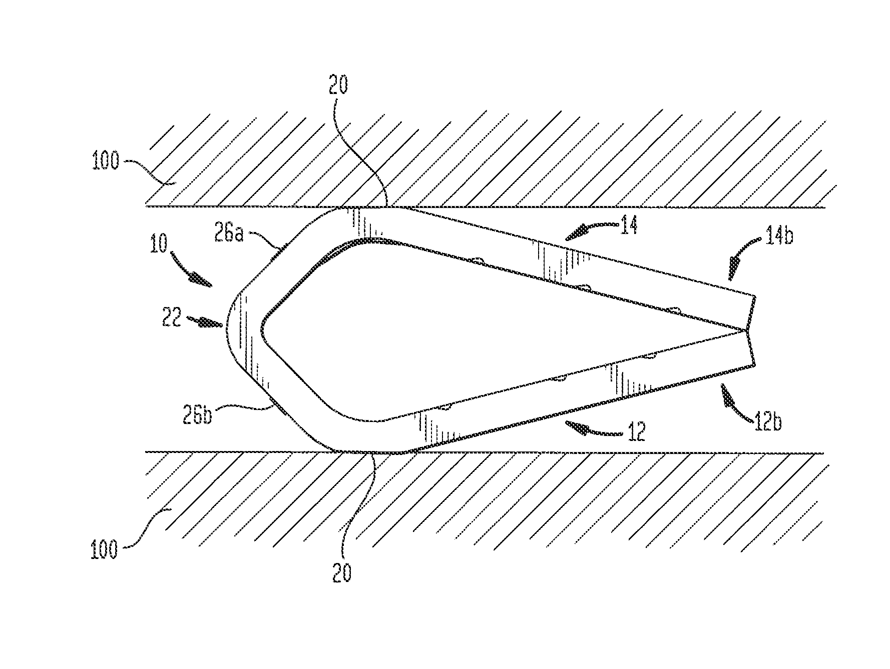
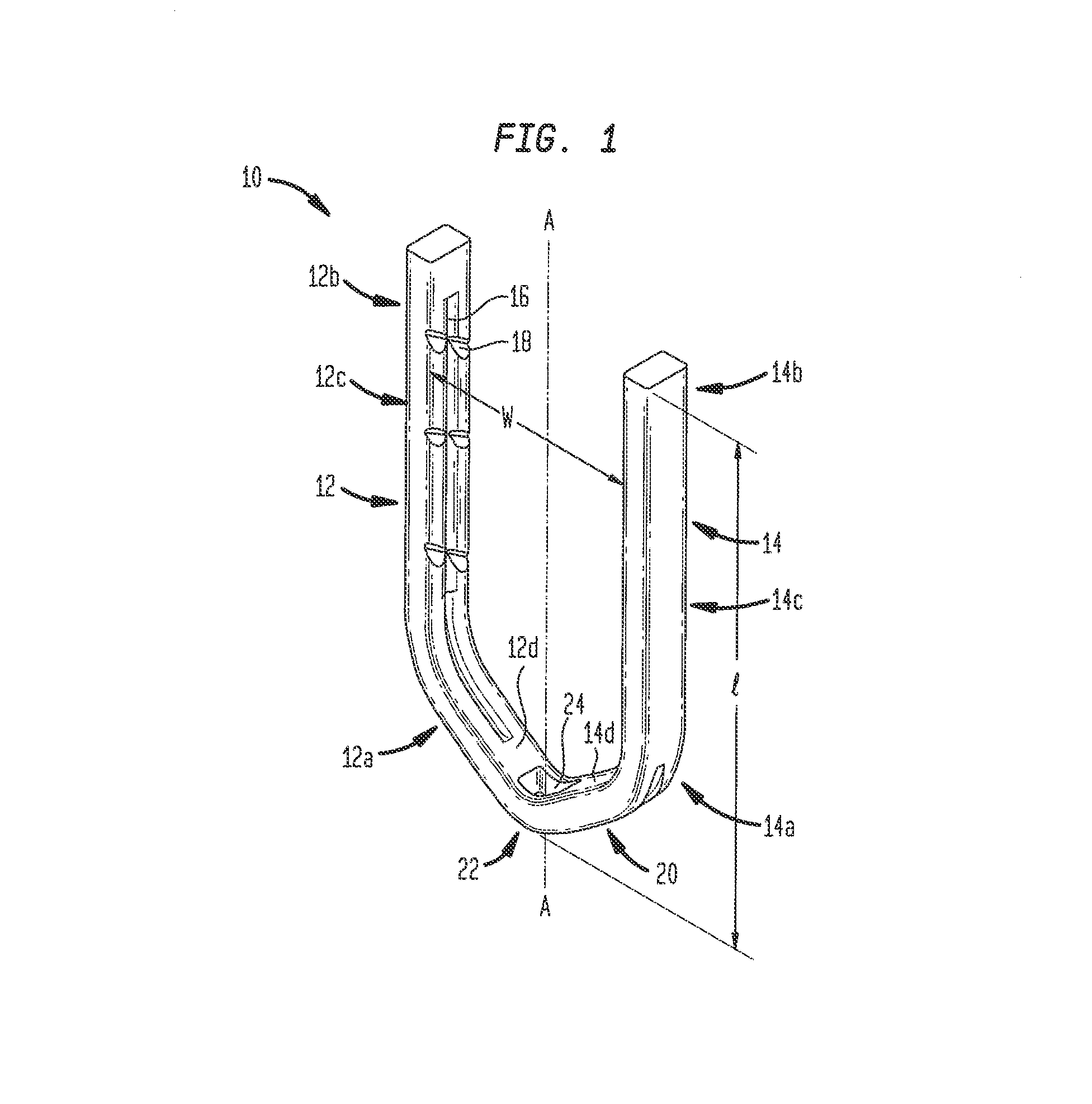
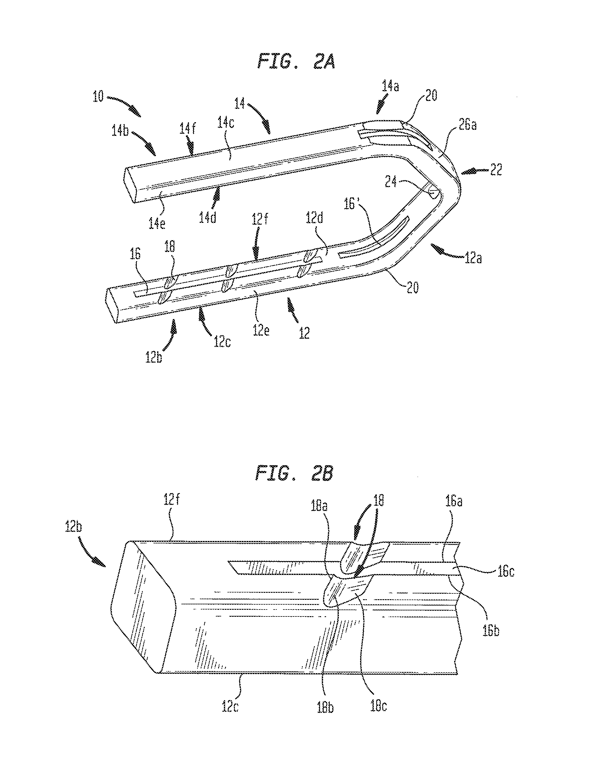
[0036]Certain exemplary embodiments will now be described to provide an overall understanding of the principles of the structure, function, manufacture, and use of the devices and methods disclosed herein. One or more examples of these embodiments are illustrated in the accompanying drawings. Those skilled in the art will understand that the devices and methods specifically described herein and illustrated in the accompanying drawings are non-limiting exemplary embodiments and that the scope of the present invention is defined solely by the claims. The features illustrated or described in connection with one exemplary embodiment may be combined with the features of other embodiments. Such modifications and variations are intended to be included within the scope of the present invention.

[0037]The present invention provides various devices for ligating tissue, such as vessels, other tubular ducts, and the like. FIGS. 1-4C illustrate exemplary embodiments of a clip disclosed herein in ...


PUM


Abstract

A method of applying a surgical clip, wherein the clip has a rigid portion with a pair of opposed first and second leg members having proximal and distal ends and a knee portion formed therebetween. The clip also has an apex with opposed ends joining the proximal ends of the first and second leg members, and a compliant portion formed on an inner surface of at least one of the first and second leg members. The method includes the step of placing the opposed first and second leg members around a tissue to be ligated, and deforming the opposed first and second leg members towards each other. The method further comprises releasing the first and second leg members to cause a separation of the first and second leg members, wherein the separation is less than the total of thickness of the compliant portion and the thickness of the tissue within the first and second leg members.

Description

FIELD OF THE INVENTION[0001]The present invention relates to surgical instruments and in particular to surgical clips and methods used for ligating vessels, other ducts, and the like.BACKGROUND OF THE INVENTION[0002]During many surgical procedures, the surgeon will have to close or ligate various blood vessels and other ducts before severing them in order to prevent excessive bleeding, and reduce the risk of other complications to the patient. One ligation technique is to tie a suture about the vessel to close the vessel. Alternatively, a surgeon can place a clip having a pair of legs connected at their proximal ends about the vessel, and urge or squeeze the legs together to close the vessel.[0003]One drawback associated with some current clips used for ligating vessels is that the legs of the clip may tend to separate to some extent following release from a clip applier. This phenomenon is called duck-billing. Duck-billing can result in insufficient ligation of a vessel, thus leadi...

Claims


Application Information

Patent Timeline
Patent Type & Authority Applications(United States)
IPC IPC(8): A61B17/122
CPCA61B17/122A61B17/1227A61B17/128
Inventor SHELTON, IV, FREDERICK E.
Owner CILAG GMBH INT
Learn More