
Extended smart diagnostic cleat

a diagnostic cleat and smart technology, applied in vehicle testing, structural/machine measurement, instruments, etc., can solve the problems of increased maintenance costs, high operation and support costs, and mechanical faults in the wheel end, suspension and fram

Inactive Publication Date: 2014-01-16
PURDUE RES FOUND INC
View PDF4 Cites 89 Cited by
  • Summary
  • Abstract
  • Description
  • Claims
  • Application Information

AI Technical Summary

Benefits of technology

The patent is about improving methods for detecting worn or faulted components on a vehicle, and simplifying the testing process. One aspect of the invention involves an apparatus for analyzing a vehicle, which includes a first segment of driving surface that locally elevates the vehicle, and a motion sensor that provides a signal corresponding to motion of the driving surface. Another aspect involves a method of analyzing a vehicle on a roadway, which involves providing a portable segment of driving surface located proximate to a local elevational change in the roadway, and a sensor that provides a signal corresponding to the response of the segment. The patent also describes various combinations and subcombinations of these components. Overall, the invention aims to provide more effective ways for detecting issues with vehicles and ensuring safe driving habits.

Problems solved by technology

As a result, mechanical faults can occur in the wheel ends, suspension, and frame.
The occurrence of faults in ground vehicles leads to high operation and support costs.
However, the run-to-failure approach can result in increased maintenance costs because an entire subsystem (suspension) may need to be replaced instead of just one damaged component (tie bolt) if failure takes place.
Preventive maintenance can be expensive because it is based on reliability predictions of the average time to failure for a fleet of vehicles, and such predictions can be conservative.
For example, preventive maintenance is often carried out when convenient, so healthy as well as damaged system components may be replaced during these maintenance actions leading to part shortages and higher inventory costs.
There are two difficulties with this onboard condition monitoring approach.
Second, many vehicles are not equipped with sensors nor the acquisition systems to acquire, process, and store data; therefore, to implement condition-based maintenance, vehicles would need to be equipped with instrumentation leading to high costs.

Method used


Image

  • Extended smart diagnostic cleat
  • Extended smart diagnostic cleat
  • Extended smart diagnostic cleat

Examples


Embodiment Construction

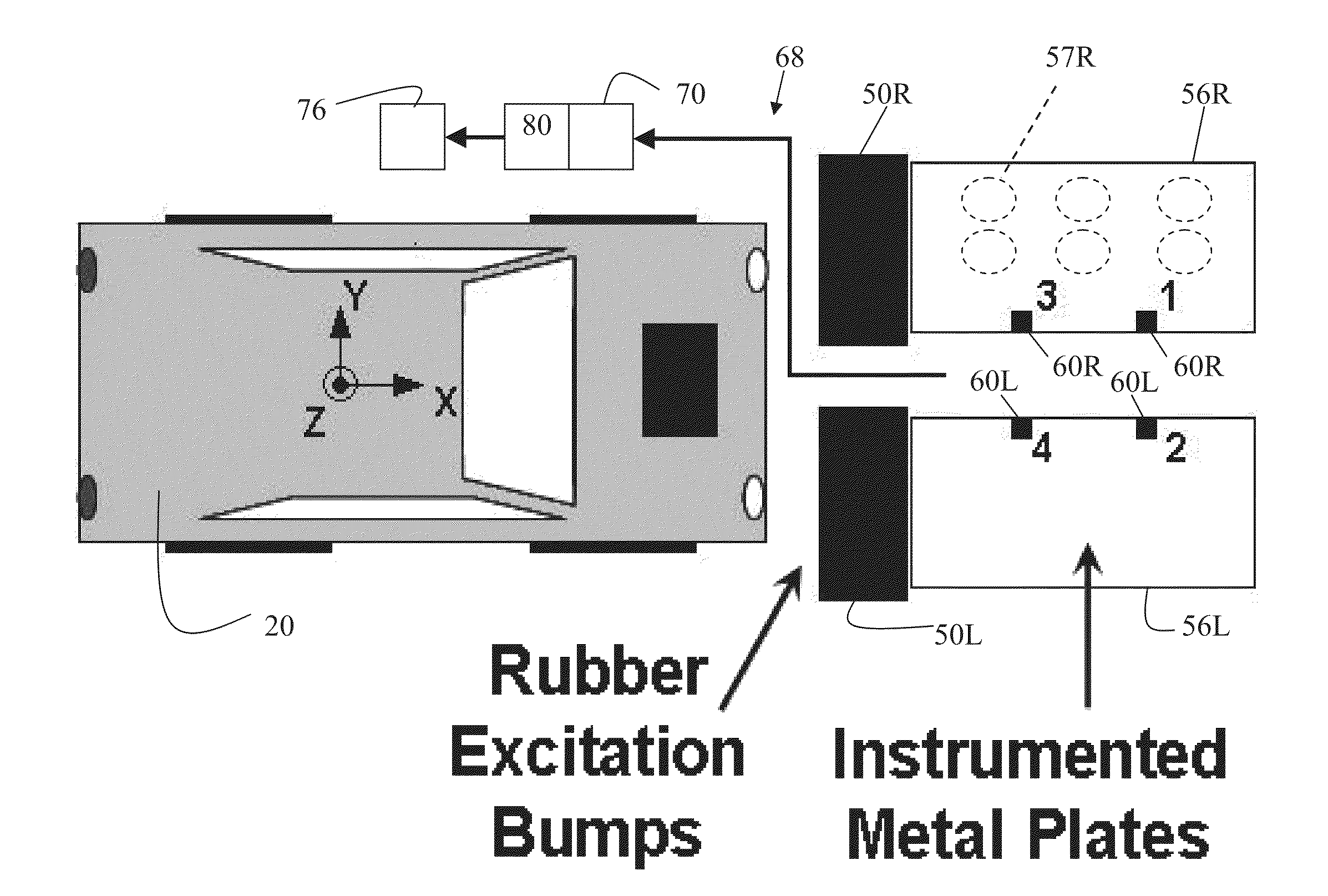
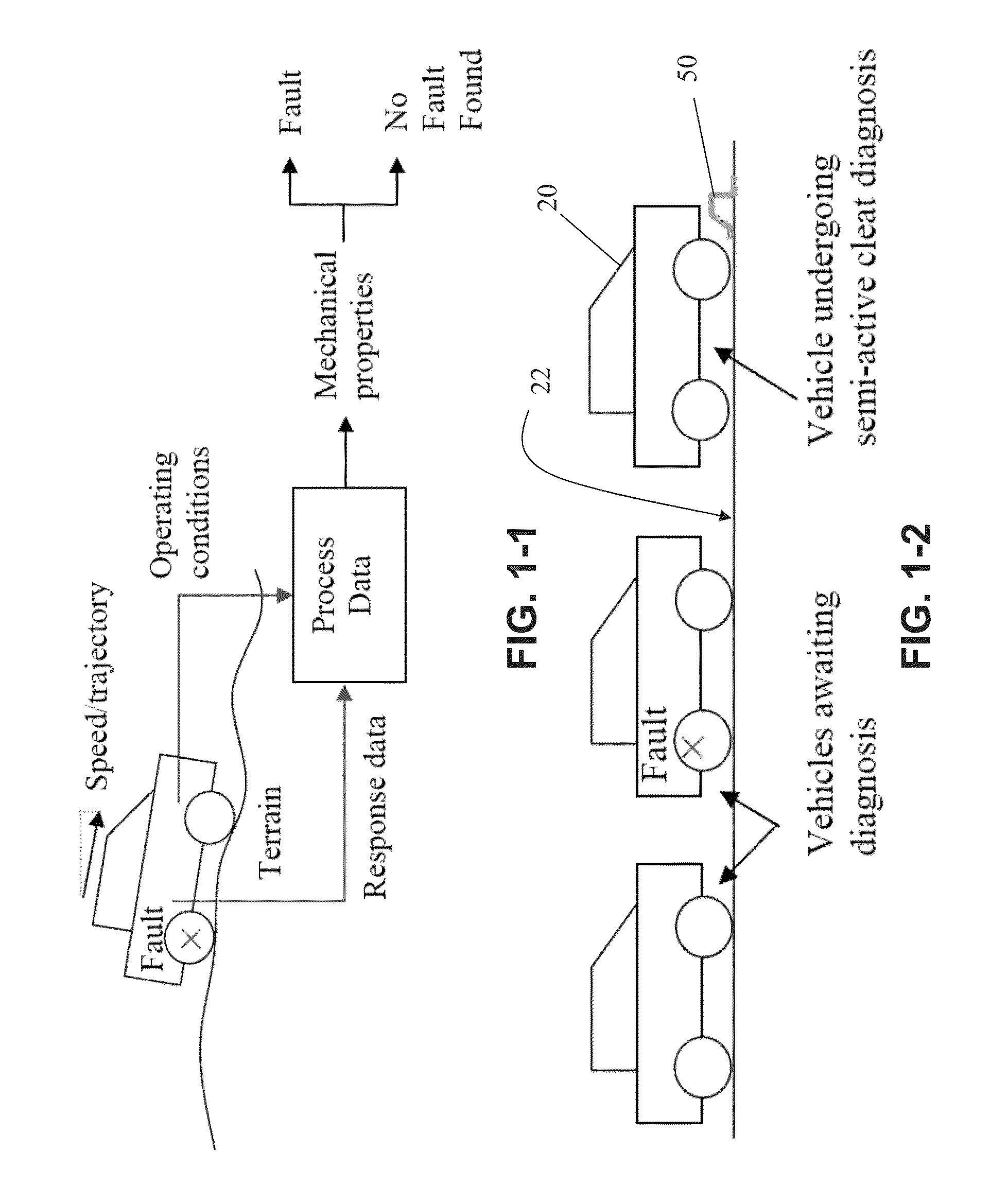
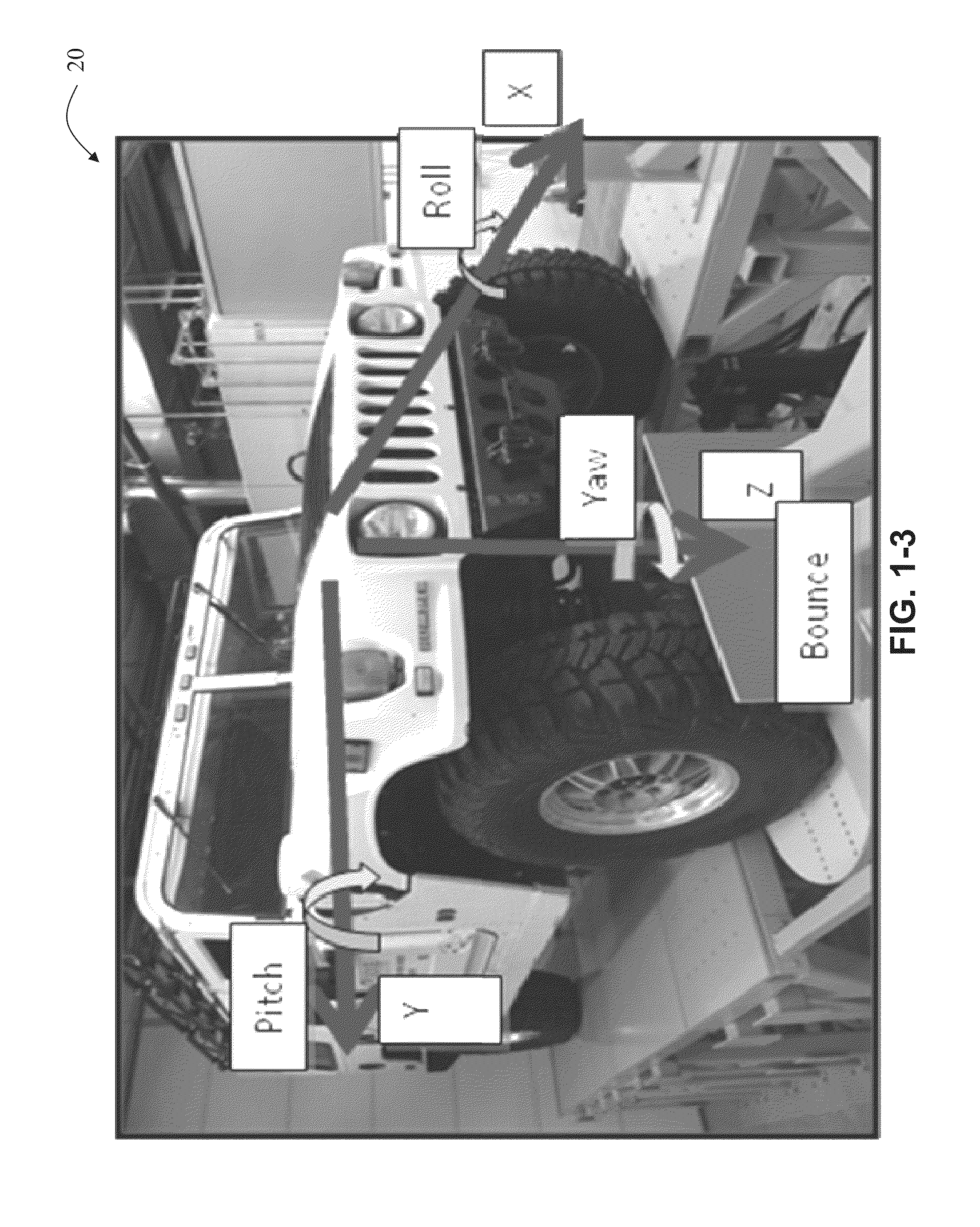
[0050]For the purposes of promoting an understanding of the principles of the invention, reference will now be made to the embodiments illustrated in the drawings and specific language will be used to describe the same. It will nevertheless be understood that no limitation of the scope of the invention is thereby intended, such alterations and further modifications in the illustrated device, and such further applications of the principles of the invention as illustrated therein being contemplated as would normally occur to one skilled in the art to which the invention relates. At least one embodiment of the present invention will be described and shown, and this application may show and / or describe other embodiments of the present invention. It is understood that any reference to “the invention” is a reference to an embodiment of a family of inventions, with no single embodiment including an apparatus, process, or composition that should be included in all embodiments, unless otherw...


PUM


Abstract

Methods and apparatus for diagnosing the condition of a vehicle. Some embodiments include providing an input to a vehicle suspension similar to an impact, and then measuring the response of the vehicle as it drives over an instrumented member. The motion of the instrumented member is recorded and corrected, and in some embodiments a fault index is calculated. The fault index can be displayed to a user to indicate a maintenance condition of the vehicles, such as a worn or broken component.

Description

CROSS REFERENCE TO RELATED APPLICATION[0001]This application claims the benefit of priority to U.S. Provisional Patent Application Ser. No. 61 / 454,800, filed Mar. 21, 2011 and U.S. Provisional Patent Application Ser. No. 61 / 602,407, filed Feb. 23, 2012, both of which are incorporated herein by reference.FIELD OF THE INVENTION[0002]Various embodiments of the present invention pertain to apparatus and methods for diagnosing the status of a multidegree of freedom system, and some embodiments pertain to analysis of wheeled vehicles.BACKGROUND[0003]Wheeled vehicles, such as the high mobility multi-purpose wheeled vehicle (HMMWV), are subjected to a wide range operational loading conditions. These vehicles are expected to function on various terrains from sand dunes to mountainous regions to highways. Also, vehicles are subjected to other varying conditions such as changes in payload, changes in tire pressure, and other factors. As a result, mechanical faults can occur in the wheel ends, ...

Claims


Application Information

Patent Timeline
Patent Type & Authority Applications(United States)
IPC IPC(8): B60W40/06B60W50/02
CPCB60W40/06B60W50/02G01M17/04
Inventor ADAMS, DOUGLAS E.DI PETTA, TIFFANY LYNNKOESTER, DAVID J.
Owner PURDUE RES FOUND INC
Learn More