
Eureka
For R&D, Eureka makes reading and utilizing patents & technical documents easy.
Eureka AIR
Designed for self-driven R&D workflows. Generate viable solutions, solve complex R&D challenges, empower your innovation with AI.

Eureka Materials
Designed for material experts only. Revolutionize your material R&D, from search, analyze, to developing new materials.

TechResearch
Generate reliable direction feasibility study reports for your R&D in just a few steps.

TechSeek
Discover and master advanced knowledge NOW. Basics, ideas, possibilities, all at once.

TechMind
As an expert in R&D Theories, TechMind can generates customized viable solutions instantly.

TechRisk
Analyze your overall solution with one click, know your potential R&D risks in advance.

TechMonitor
Get weekly tech updates, stay abreast of the latest tech innovations and key insights.
Cantilevered Table
- Summary
- Abstract
- Description
- Claims
- Application Information
AI Technical Summary
Benefits of technology
Problems solved by technology
Method used
Image

Examples
first embodiment
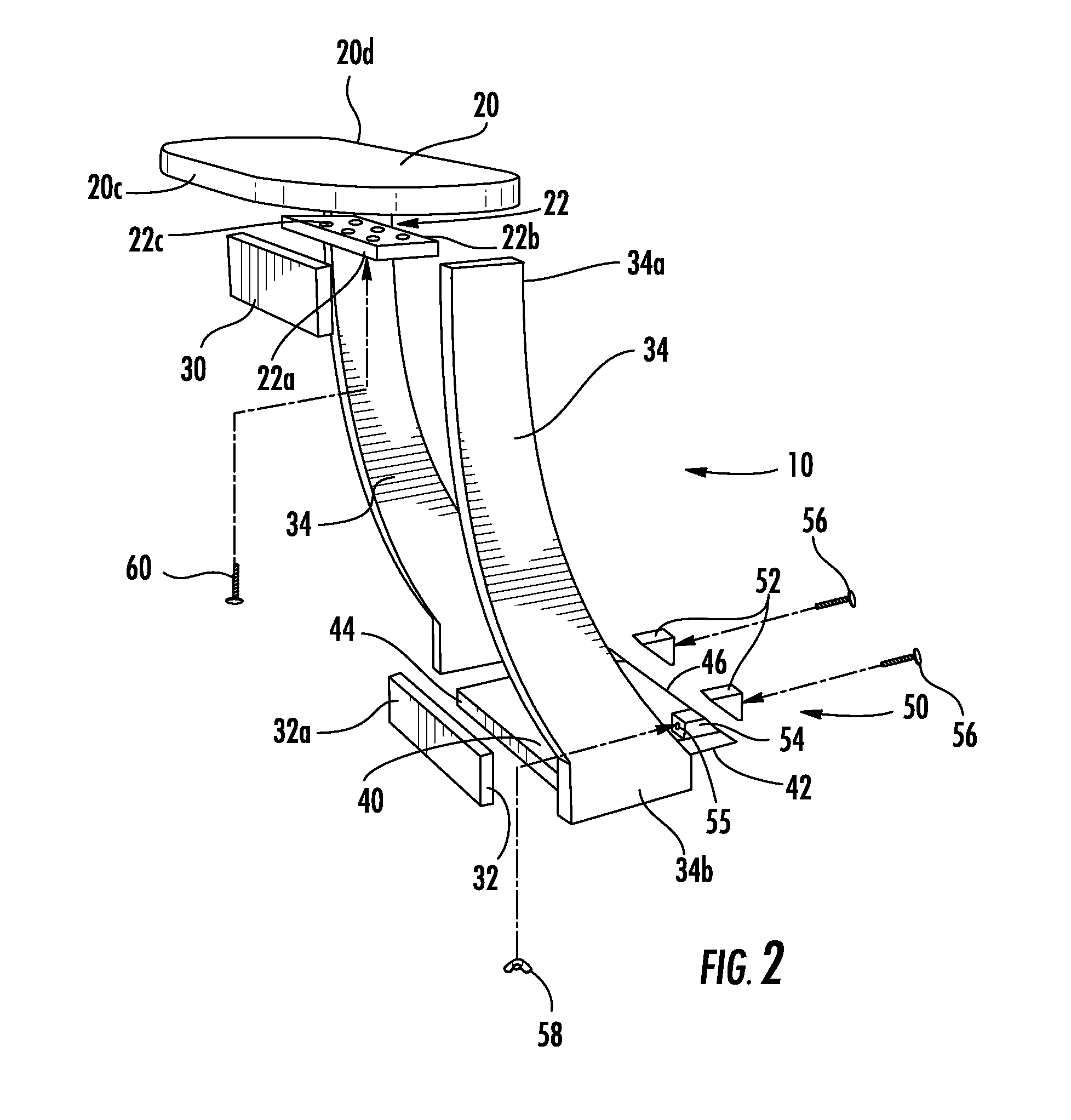
[0052]a cantilevered table 10 according to the invention is shown in FIGS. 1-8b. Looking at FIG. 2, begin assembly by using three fasteners 60, typically 1¼″ wood screws, to securely fasten a bottom end 34b of each vertical side member 34 to a lateral edge 42 of a base 40, such that the base 40 is affixed between the vertical side members 34. Attach a top support 22 to a top end 34a of the vertical side members 34 using four fasteners 60, positioning the top support 22 parallel to the base 40. Due to the curve in the vertical side members 34, the top end 34a and the affixed top support 34 will extend beyond a distal end 44 of the base 40. Looking more specifically at FIG. 4, the angle at which the bottom ends 34b of the vertical side members 34 curve away from the top ends 34a is shown as angle theta, which in the present embodiment is about 60 degrees. The value of theta can range anywhere between 20 and 90 degrees, but the inventor has found that at 60 degrees, as shown in the Fig...
second embodiment
[0054]In a second embodiment, not shown, the table 10 according to the invention may be provided without the base 40, and instead, the wedge assemblies 50 may be directly affixed to the bottom ends 34b of the vertical side members 34, and for aesthetics, to a medial side of the vertical side members 34 such that they are not visible when viewing the table in its installed position adjacent to a sofa arm rest 82.
[0055]To install the table according to the invention next to an arm rest of a sofa, the base 40 and / or the bottom ends 34b of each vertical side member 34 is placed on a floor surface 70 and slid under a desired side of the sofa 80 until each wedge assembly 50 is under a lateral support member 84 of the sofa 80. Once positioned, the wedge adjustment bolt 56 is tightened by turning the wing-nut 58, causing the upper wedge 52 to slide upwards and against the lateral support member 84 of the sofa 80 to close the gap between the lateral support member 84 and the floor surface 70...
third embodiment
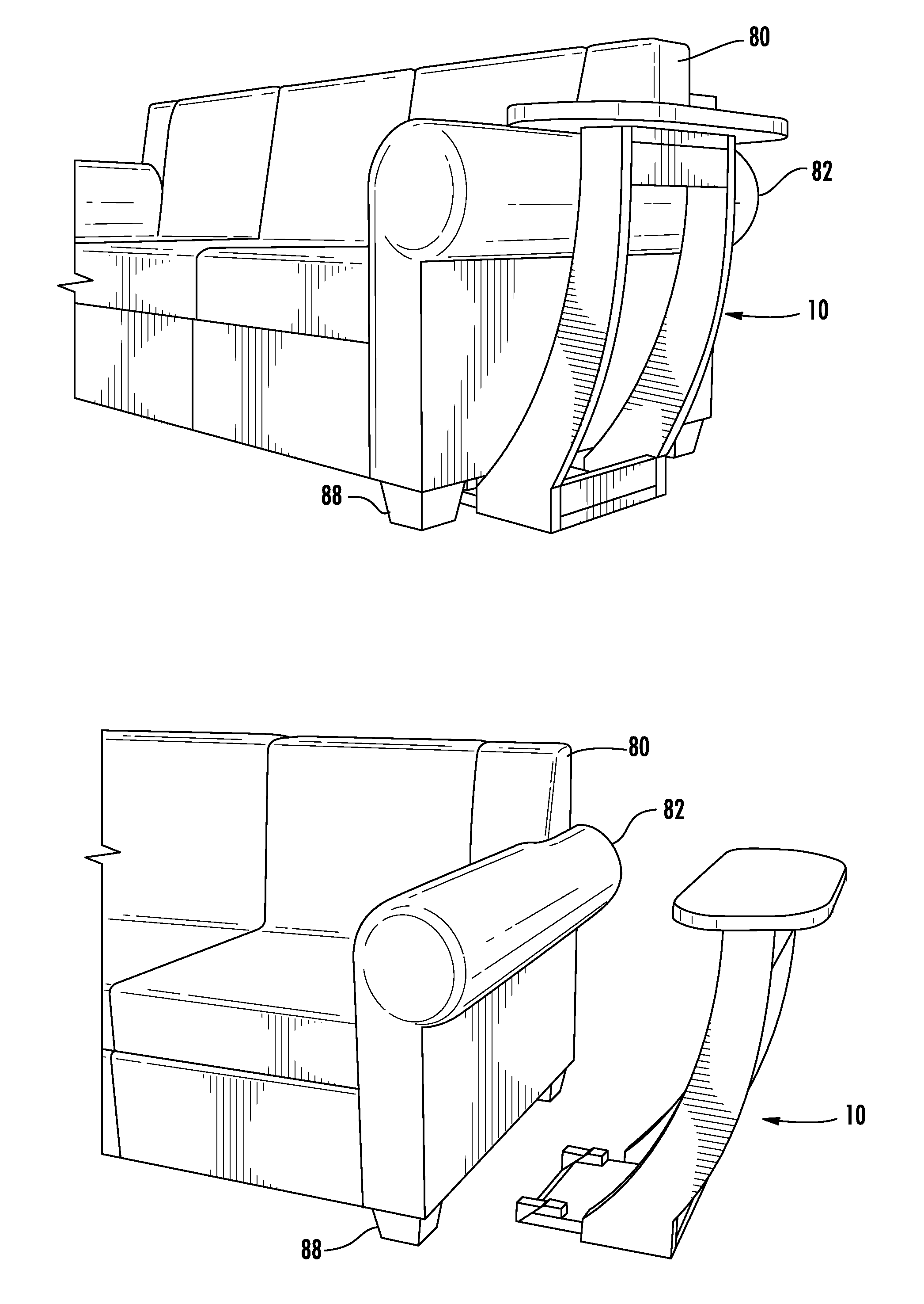
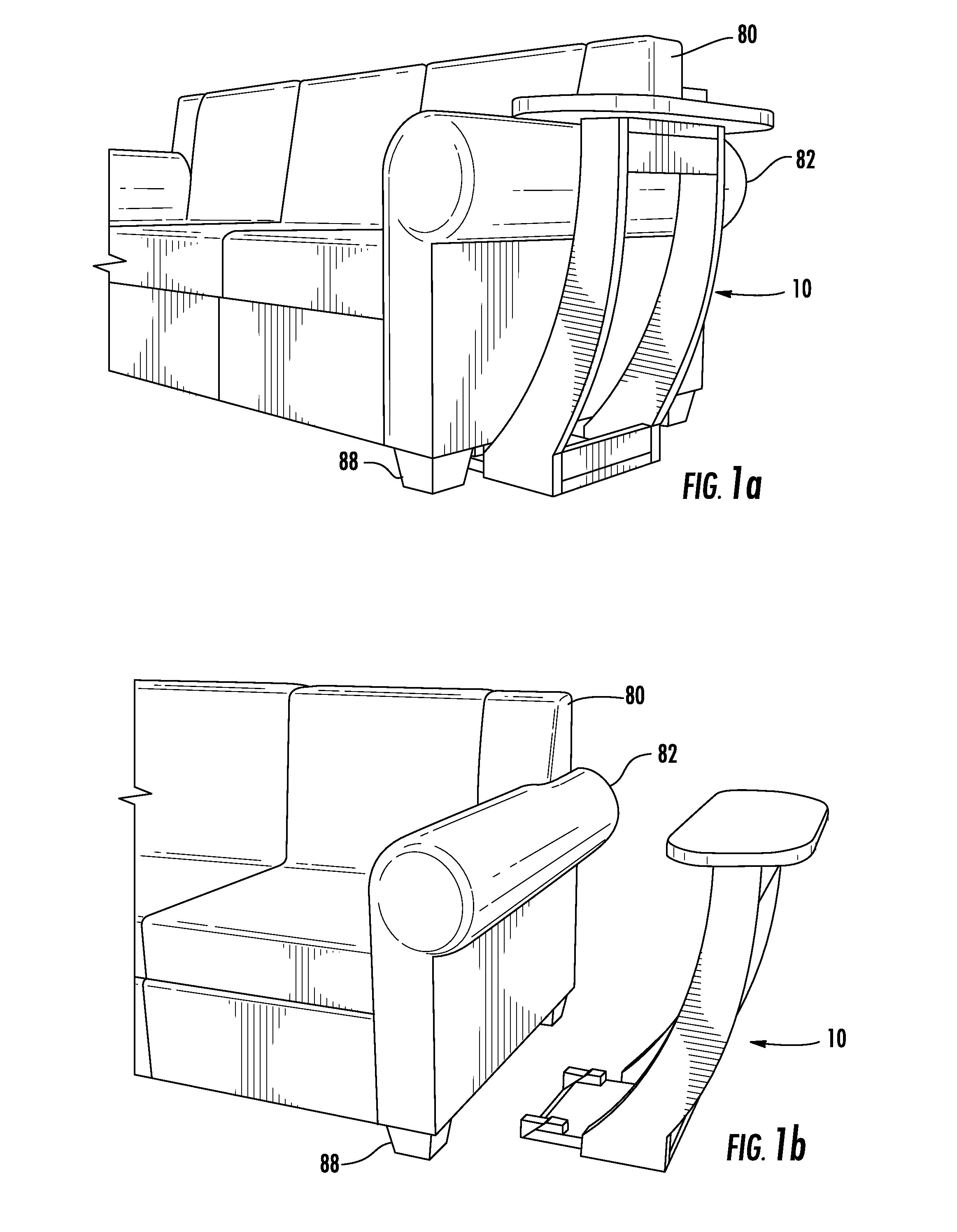
[0056]In a third embodiment shown in FIG. 8b, the table 10 according to the invention provides a narrow, elongated table top 20 installed along a back side of the sofa 80, the wedge assemblies 50 fitted against a back support member 86 (shown in FIG. 8a) of an underside of the sofa 80.
[0057]The table 10 according to the invention, unlike the prior art cantilevered tables, is not self supporting, and requires the wedge assemblies 50 to be secured between the floor surface 70 and the lateral 84 or back support member 86 of the underside of the sofa 80. The sofa 80 anchors the table 10 to the floor surface 70, and given the weight of a typical sofa compared to the table 10, the sofa will most often weigh enough to effectively balance the table top 20 (and things placed upon it, such as plates of food) and render the table secure and stable.
[0058]Paint and / or stain grade wood is suitable for construction of the table as described in the embodiments within, however, a mix of different ma...
PUM
 Abstract
Description
Claims
Application Information
 - R&D Engineer
- R&D Manager
- IP Professional
- Industry Leading Data Capabilities
- Powerful AI technology
- Patent DNA Extraction
Browse by: Latest US Patents, China's latest patents, Technical Efficacy Thesaurus, Application Domain, Technology Topic, Popular Technical Reports.
© 2024 PatSnap. All rights reserved.Legal|Privacy policy|Modern Slavery Act Transparency Statement|Sitemap|About US| Contact US: help@patsnap.com