Device for reducing flow noise and valve
a flow noise and valve technology, applied in the direction of mechanical equipment, pipe elements, transportation and packaging, etc., can solve the problems of significant flow velocity in the generation of noise and the increase of the noise level produced by the free jet, and achieve the effect of reducing flow noise in flow control
- Summary
- Abstract
- Description
- Claims
- Application Information
AI Technical Summary
Benefits of technology
Problems solved by technology
Method used
Image
Examples
first embodiment
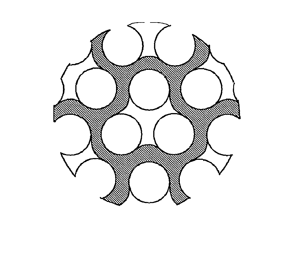
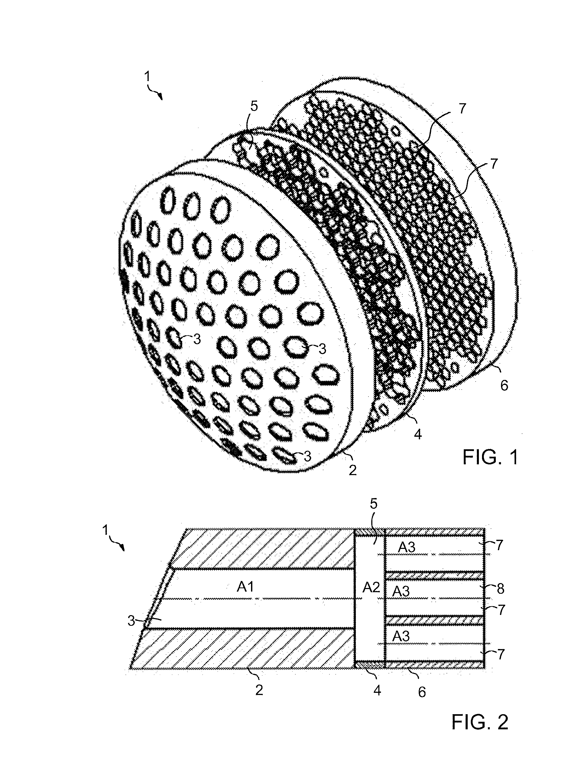
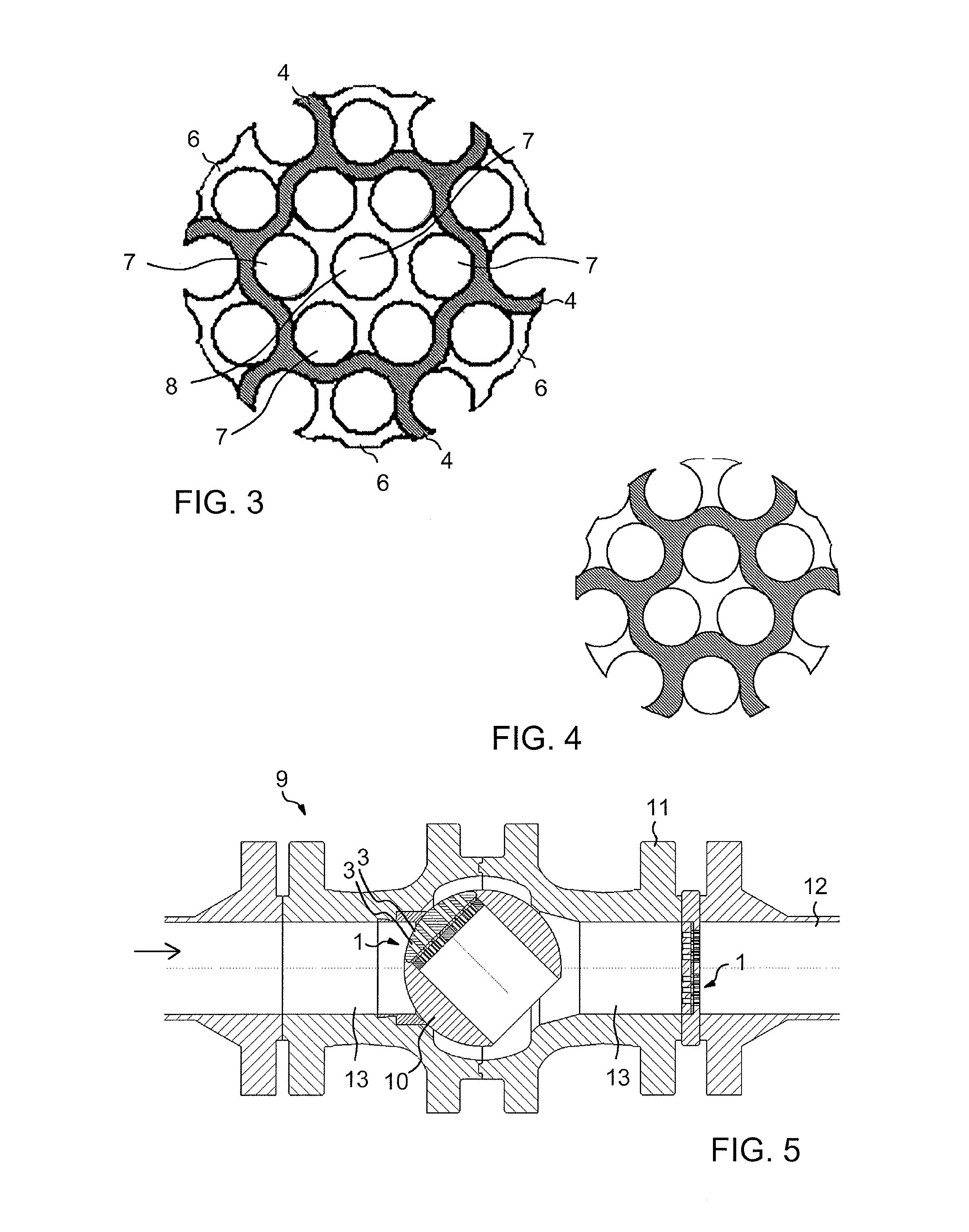
[0018]FIGS. 1 to 3 illustrate a device. FIG. 1 is an exploded view of the device 1, FIG. 2 is a partial section of the device 1 of the figure, and FIG. 3 shows the design of the transverse flow area of chambers.
[0019]In the following, it is by way of example assumed that the device is implemented by means of three parts (e.g. three plates) to be placed against one another, as shown by way of example in the figures. However, it is to be noted that this is not necessary in all embodiments since the necessary apertures and chambers may also be implemented in other ways, e.g. by machining both inlet and outlet apertures as well as chambers in some of the shown parts.
[0020]In the exemplary case of FIG. 1, a part 2 situated on the left has an inlet surface which is provided with a plurality of inlet apertures 3 for receiving a fluid flow. A middle part 4 is provided with chambers 5, in which case the inlet apertures 3 are chamber-specific, i.e. each inlet aperture opens up into one chambe...
second embodiment
[0040]FIG. 8 illustrates the device. The embodiment of FIG. 8 largely corresponds to the embodiment of FIG. 1, wherefore the embodiment of FIG. 8 will be explained in the following primarily by disclosing differences from the embodiment of FIG. 1.
[0041]The left half (the inlet aperture 3, the chamber 5 and the outlet apertures 7) of the device 1′ of FIG. 8 matches completely the device 1 shown in FIG. 1. In this embodiment, however, more than one corresponding device is arranged successively. Thus, the outlet apertures 7 simultaneously form inlet apertures for a second chamber 5′ such that each outlet aperture 7 leads to a second individual chamber 5′ of its own. As distinct from FIG. 8, it is also feasible that more than one outlet aperture 7 leads to each of the second chambers 5′. Each of the second chambers 5′, in turn, is provided with individual outlet apertures 7′ of its own, wherefrom the flow is allowed to advance from said second chamber 5′. The cross-sectional area of eac...
third embodiment
[0042]FIG. 9 illustrates the device. The embodiment of FIG. 9 largely corresponds to the embodiment of FIG. 1, wherefore in the following the embodiment of FIG. 9 will be explained primarily by disclosing differences from the embodiment of FIG. 1.
[0043]The left half (the inlet aperture 3, the chamber 5 and the outlet apertures 7) of the device 1″ of FIG. 9 matches completely the device 1 shown in FIG. 1. However, in this embodiment, the outlet apertures 7 simultaneously form inlet apertures for a second chamber 5″. Only one single second chamber 5″ is in use which receives the flow from all outlet apertures 7 of the chamber 5. From the second chamber 5″ the flow is allowed to advance via a plurality of outlet apertures 7.
PUM
 Abstract
Description
Claims
Application Information
 - R&D
- Intellectual Property
- Life Sciences
- Materials
- Tech Scout
- Unparalleled Data Quality
- Higher Quality Content
- 60% Fewer Hallucinations
Browse by: Latest US Patents, China's latest patents, Technical Efficacy Thesaurus, Application Domain, Technology Topic, Popular Technical Reports.
© 2025 PatSnap. All rights reserved.Legal|Privacy policy|Modern Slavery Act Transparency Statement|Sitemap|About US| Contact US: help@patsnap.com


