Motion blur compensation

Active Publication Date: 2014-01-23
3SHAPE AS
View PDF20 Cites 20 Cited by
  • Summary
  • Abstract
  • Description
  • Claims
  • Application Information

AI Technical Summary

Benefits of technology

[0179]In spatial correlation independent knowledge of the pattern configuration allows for calculating the correlation measure at each group of light sensing. For a spatially periodic illumination this correlation measure can be computed without having to estimate the cosine and sinusoidal part of the light intensity oscillation. The knowledge of the pattern configuration may be obtained prior to the 3D scanning.
[0180]Compared to temporal correlation, spatial correlation has the advantage that no moving pattern is required. This implies that knowledge of the pattern configuration may be obtained prior to the 3D scanning. Conversely, the advantage of temporal correlation is its higher resolution, as no pixel grouping is required.
[0181]All correlation principles, when embodied with an image sensor that allows very high frame rates, enable 3D scanning of objects in motion with little motion blur. It also becomes possible to trace moving objects over time (“4D scanning”)

Problems solved by technology

It remains a problem to provide motion blur compensation in 3D scanning, such as optical scanning, of objects in order to obtain excellent virtual 3D models of the scanned objects.
Motion sensors with limited accuracy can still provide a first guess for a software-based stitching/registration of partial scans based on, e.g., the Iterative Closest Point class of algorithms, resulting in reduced computation time.
Prior art does not provide for motion compensation in relation to a 3D scanner where focus plane images can be acquired while the handheld scanner, and thereby, sensor is movin

Method used


Image

  • Motion blur compensation
  • Motion blur compensation
  • Motion blur compensation

Examples


Example

[0231]In the following description, reference is made to the accompanying figures, which show by way of illustration how the invention may be practiced.

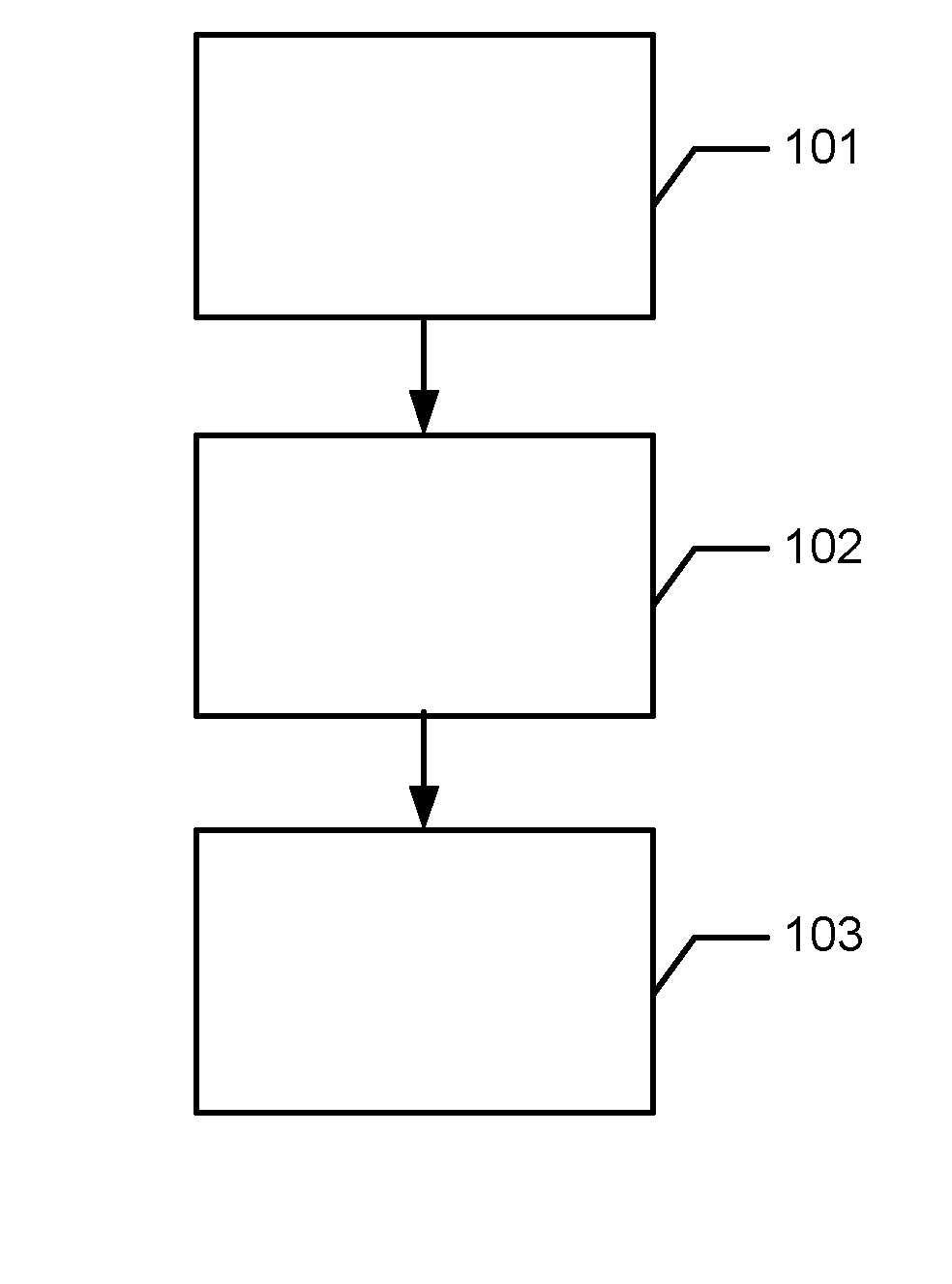
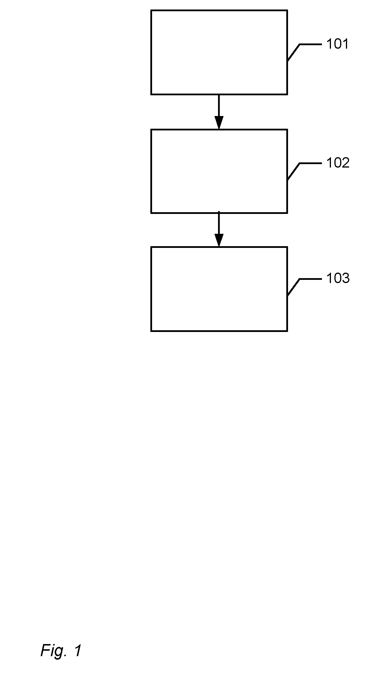
[0232]FIG. 1 shows a flowchart of a method for compensating for motion blur when performing a 3D scanning of at least a part of an object by means of a 3D scanner.

[0233]The motion blur occurs because the scanner and the object are moved relative to each other while the scanning is performed. The motion blur compensation comprises that:

[0234]In step 101 it is determined whether there is a relative motion between the scanner and the object during the acquisition of the sequence of focus plane images.

[0235]In step 102 a motion compensation based on the determined motion is performed, if a relative motion is determined.

[0236]In step 103 a 3D surface is generated from the sequence of focus plane images.

[0237]In some cases, a first 3D surface has been generated prior to steps 101-103 and the motion compensation in step 102 and / or the gener...


PUM


Abstract

Disclosed is a method for compensating for motion blur when performing a 3D scanning of at least a part of an object by means of a 3D scanner, where the motion blur occurs because the scanner and the object are moved relative to each other while the scanning is performed, and where the motion blur compensation comprises:—determining whether there is a relative motion between the scanner and the object during the acquisition of the sequence of focus plane images;—if a relative motion is determined, performing a motion compensation based on the determined motion; and—generating a 3D surface from the sequence of focus plane images.

Description

FIELD OF THE INVENTION[0001]This invention generally relates to a system and a method for compensating for motion blur. More particularly, the invention relates to motion blur compensation in 3D scanning of at least a part of an object by means of a 3D scanner.BACKGROUND OF THE INVENTION[0002]Motion blur compensation is generally known from 2D scanning or imaging of objects.[0003]It remains a problem to provide motion blur compensation in 3D scanning, such as optical scanning, of objects in order to obtain excellent virtual 3D models of the scanned objects.SUMMARY[0004]Disclosed is a method for compensating for motion blur when performing a 3D scanning of at least a part of an object by means of a 3D scanner, where the motion blur occurs because the scanner and the object are moved relative to each other while the scanning is performed, and where the motion blur compensation comprises:[0005]determining whether there is a relative motion between the scanner and the object during the ...

Claims


Application Information

Patent Timeline
IPC IPC(8): H04N13/00
CPCH04N13/0007G06T2207/10028G06T2207/10148G06T2207/30036G06T5/003G06T2207/20201G06T7/30G06T7/571G06T5/50G06T2207/10016H04N23/6812H04N13/106
Inventor FISKER, RUNEOJELUND, HENRIKVAN DER POEL, MIKEHANSEN, KRISTIAN EVERSGAARDE, ANDERS
Owner 3SHAPE AS
Why Eureka
Try Eureka