Smart pause for distributed switch fabric system

a fabric system and distributed switch technology, applied in data switching networks, frequency-division multiplexes, instruments, etc., can solve problems such as not fully realizing the potential of these flow control mechanisms

a fabric system and distributed switch technology, applied in data switching networks, frequency-division multiplexes, instruments, etc., can solve problems such as not fully realizing the potential of these flow control mechanisms

US20140022901A1Active Publication Date: 2014-01-23CISCO TECH INC

Image

  • Smart pause for distributed switch fabric system
  • Smart pause for distributed switch fabric system
  • Smart pause for distributed switch fabric system

Examples


example embodiments

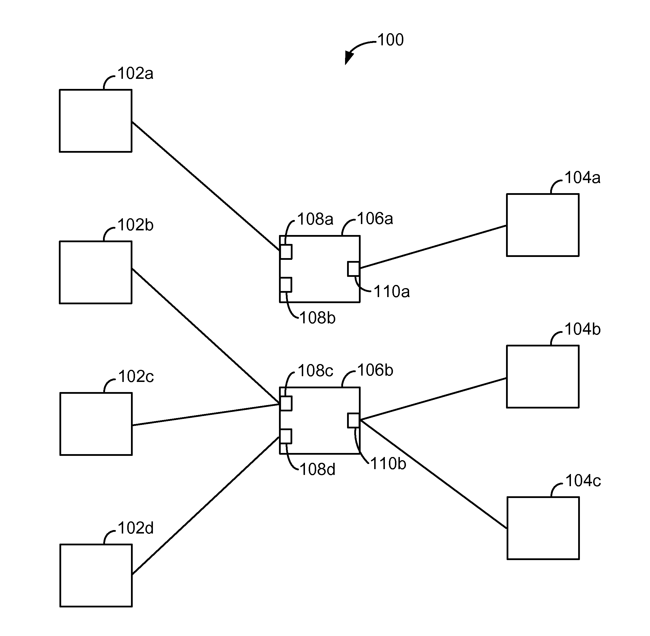
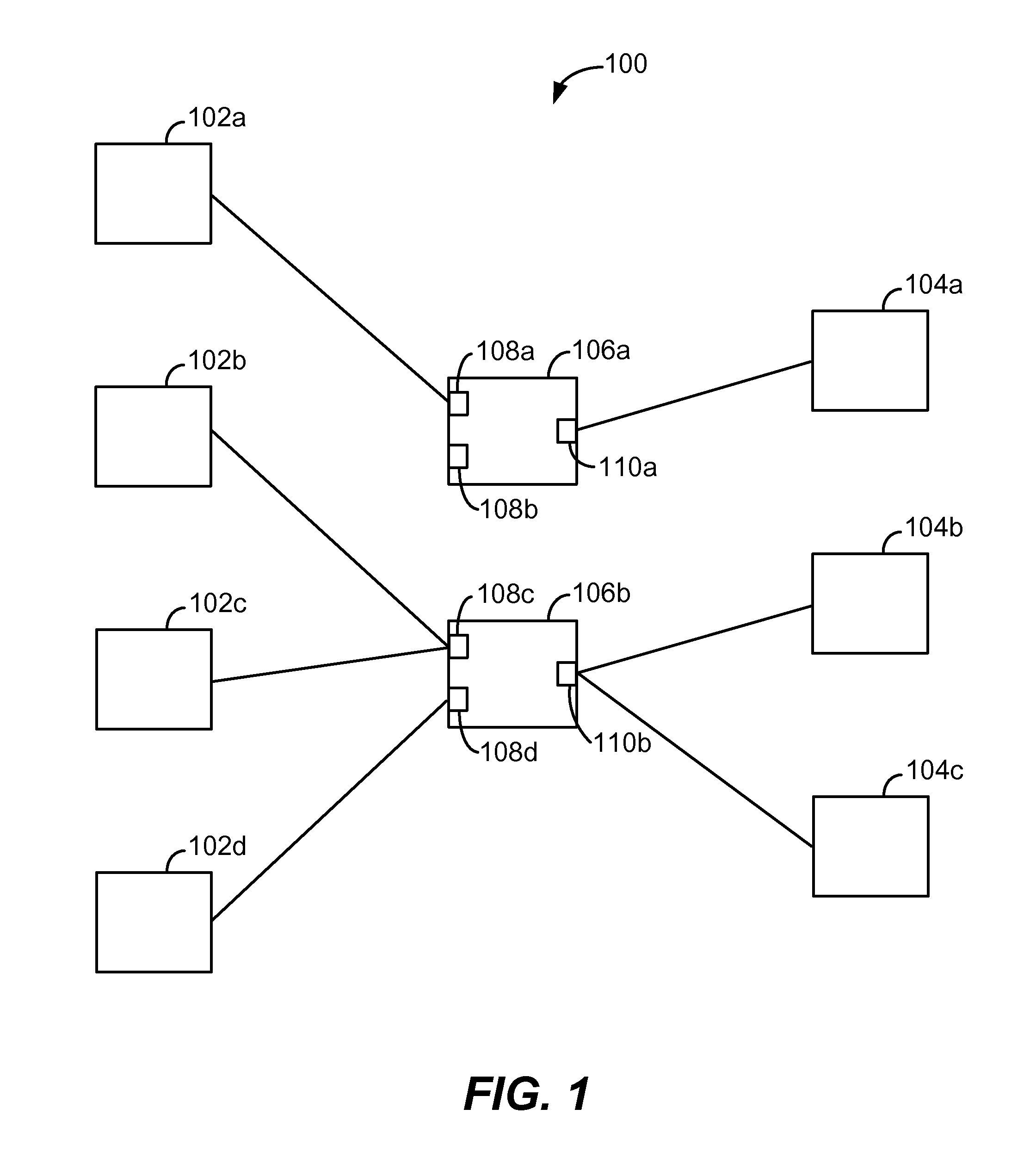
[0019]In modern networks, a switch or other network device may include a plurality of hardware and / or software modules. For example, a plurality of I / O buffer modules may be used to implement I / O interfaces of a network node. A line card is an example of such an I / O buffer module. These I / O buffer modules may be located on different chips or integrated circuits. In alternative embodiments, one or more of these buffer modules may be located on the same chip or integrated circuit.

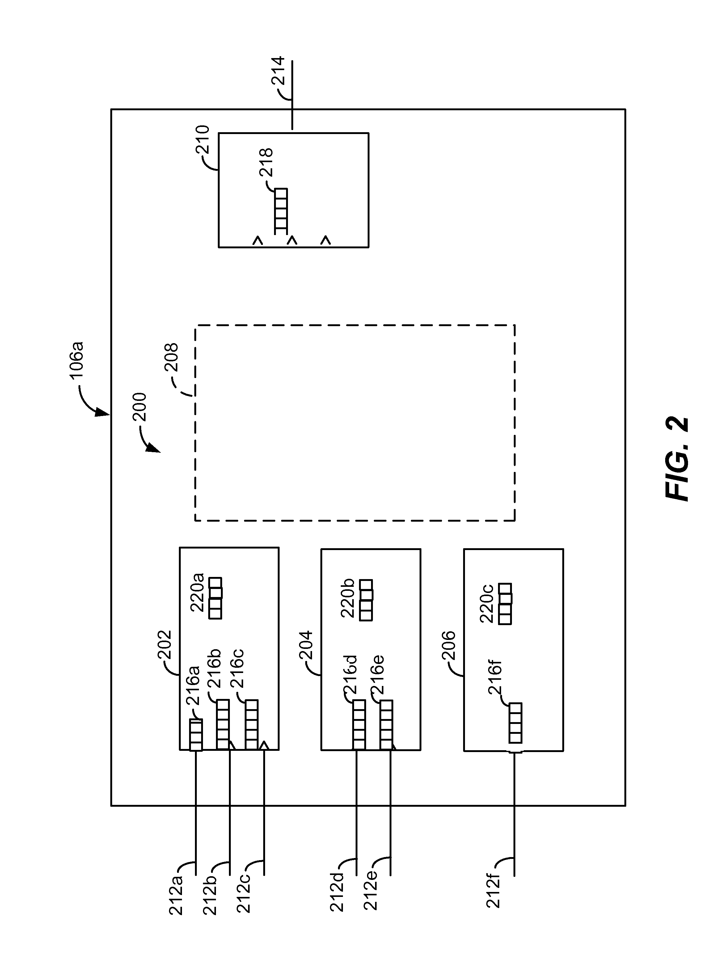
[0020]Each of the above described I / O buffer modules may be associated with a plurality of ingress or egress ports (or ports functioning as both ingress and egress ports). Additionally, each of the I / O buffer modules may maintain a plurality of actual or virtual queues, each queue corresponding, for example, to one of the associated ports. The ingress and egress modules may be interconnected by a switch fabric or other interconnection mechanism of the network device. Examples of such interconnection mechanism...


PUM


Abstract

Techniques for improving the performance of flow control mechanisms such as Pause are provided. The techniques provide for maintaining a fair distribution of available bandwidth while also allowing for fewer packet drops, and maximizing link utilization, in a distributed system. For example, in one embodiment, techniques are provided for achieving a fair share allocation of an egress port's bandwidth across a plurality of ingress ports contending for the same egress port.

Description

TECHNICAL FIELD[0001]The present disclosure relates generally to the field of flow control in computer networks, and in particular to techniques relating to Pause or similar flow control mechanisms for addressing network congestion.BACKGROUND[0002]Flow control mechanisms are used to prevent and reduce congestion in computer networks. Some flow control mechanisms operate by temporarily stopping transmission of data to congested nodes of a computer network until congestion at those nodes is reduced. One flow control mechanism of this kind developed for Ethernet networks, for example, is the Pause frame defined by the IEEE 802.3x standard. A congested node may send a Pause message to entities sending packets to it. The Pause message indicates that the sending source entities should temporarily suspend transmission of packets to that congested node. In one example, in response, source entities may stop transmission of packets to that congested node for a time duration specified in the P...

Claims


Application Information

Patent Timeline
23 Jan 2014
Publication
US20140022901A1
IPC
H04L12/56
CPC
H04L47/266; H04L49/15
Inventors
SUZUKI, HIROSHI; PAN, RONG