Method for providing the Identity of an Apparatus in a Communications Network and Apparatus Thereof

a technology of communication network and identity, applied in the field of mobile telecommunication networks, can solve problems such as bad radio conditions, achieve the effects of reducing average radio-transmission power, enhancing cell capacity, and long battery li

Active Publication Date: 2014-01-23
BEIJING XIAOMI MOBILE SOFTWARE CO LTD
View PDF9 Cites 10 Cited by
  • Summary
  • Abstract
  • Description
  • Claims
  • Application Information

AI Technical Summary

Benefits of technology

[0003]Apart from this main goal of coverage extension, introducing relay concepts can also help in (a) providing a high-bit-rate coverage in high shadowing environments, (b) reducing average radio-transmission power at a user equipment (UE), thereby leading to long battery life, (c) enhancing the cell capacity and effective throughput, e.g., increasing cell-edge capacity and balancing cell load and (d) enhancing the overall performance and deployment cost of a Radio Access Network (RAN).
[0004]There are many kinds of relay systems proposed starting from the simplest amplify / forward RN, which is applied e.g. in single frequency Digital Video Broadcasting-Handhelds (DVB-H) networks ending up to the most complex one, which utilizes a network coding to improve the overall performance. The most common type of RN that is proposed for use of RN in mobile networks (also known as cellular relaying) is a detect / forward type of RN, where an input signal is detected and retransmitted using the same procedure as in the original transmission. Relaying can be realized at the different layers of a protocol stack, which layers are described by the well known Open Systems Interconnection Reference Model (OSI model). A simple amplify and forward relaying can be realized at the Layer 1 of the protocol stack where the RN is required to have only (some part of) the PHY layer. Layer 2 RNs, which include the protocol stack up to the Media Access Control (MAC) / Radio Link Control (RLC) layers, enable the possibility of doing decentralized radio resource management. Layer 3 (L3) or higher layer RNs, also known as Type 1 RN or self-backhauling RN, can be considered by a UE as wireless base stations and support all the protocol layers of normal base stations. That is, a L3 RN is required to have all the essential LTE release 8 eNB cell parameters and to broadcast them so that it can be recognized as a normal eNB cell by UEs.

Problems solved by technology

Further, areas can be covered which without using RN would suffer from bad radio conditions.

Method used


Image

  • Method for providing the Identity of an Apparatus in a Communications Network and Apparatus Thereof
  • Method for providing the Identity of an Apparatus in a Communications Network and Apparatus Thereof
  • Method for providing the Identity of an Apparatus in a Communications Network and Apparatus Thereof

Examples


Embodiment Construction

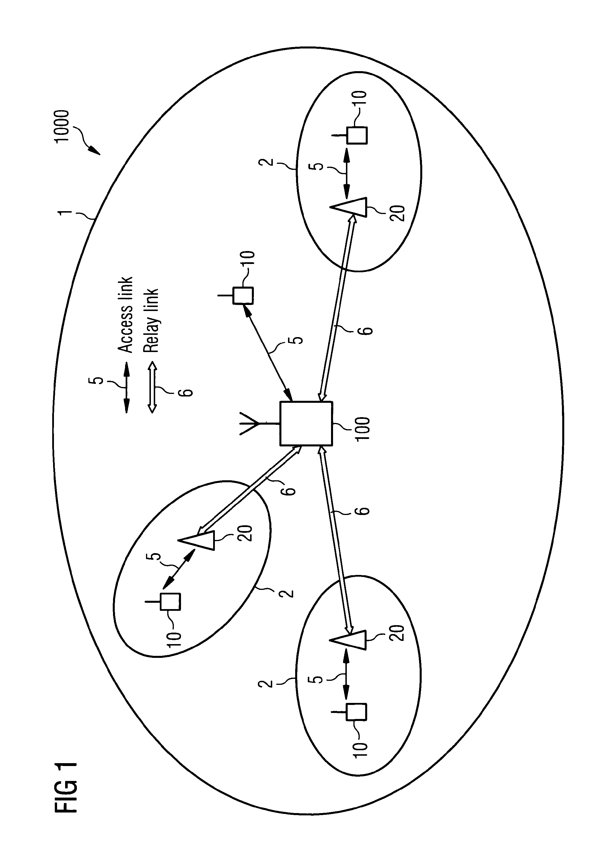
[0020]FIG. 1 shows a typical deployment of RNs in a cell 1 of a communications network 1000. In order to aid the understanding of the proposed invention only one exemplary cell 1 has been depicted. It is of course well known that in communications network 1000 where numerous UEs can be present, more than one cell 1 will exist. Communications network 1000 comprises an access node 100 providing coverage in cell 1 and access to a core network (CN) which is not illustrated. Within cell 1, RNs 20 are also present and allow for the coverage of cell 1 to be extended via the creation of RN cells 2. UEs 10 that are present within cell 1 can either be connected directly to access node 100 over an access link 5 or be connected to an RN 20 also over an access link 5. RNs 20 are in turn connected to access node 100 over a communication link 6 namely a relay link or equivalently in the case of a L3 type of relay this is also named a backhaul link.

[0021]Communications network 1000, can be an LTE o...


PUM


Abstract

The invention relates to an access node in a communications network that is adapted for providing an identifier for a relay node including receiver means arranged to receive a message from the relay node, the message requesting an establishment of an interface over a communication link, checking means arranged to check data fields included in the message received, generating means arranged to generate the identifier, and transmitting means arranged to transmit the generated identifier to the relay node over the interface connection of communication link.

Description

FIELD OF THE INVENTION[0001]The present invention relates to the technical field of mobile telecommunication networks. In particular, the present invention relates to a method for providing the identity of an apparatus within a relay enhanced mobile telecommunication network when an apparatus connects to the network. Further, the present invention relates to an apparatus which is adapted to carry out the mentioned method.SUMMARY OF THE INVENTION[0002]In order to allow for cost efficient and flexible deployment solutions, within the third generation partnership project (3GPP) relaying is investigated as one of the new technologies for Long Term Evolution (LTE) networks and in particular for Long Term Evolution Advanced (LTE-A) networks. It has been shown that with the usage of Relay Nodes (RN) the spatial coverage and / or the capacity of a base station (BS) or of an eNodeB (eNB) can be significantly increased. Further, areas can be covered which without using RN would suffer from bad ...

Claims


Application Information

Patent Timeline
Patent Type & Authority Applications(United States)
IPC IPC(8): H04W16/26
CPCH04W16/26H04B7/2606H04W8/26H04W84/047H04W92/20
Inventor REDANA, SIMONEWALDHAUSER, RICHARDBAZAR, ISMAN
Owner BEIJING XIAOMI MOBILE SOFTWARE CO LTD
Why Eureka
Try Eureka