
Roof rack for a motor vehicle, and a method for operating a controller of a motor vehicle and a corresponding controller

Active Publication Date: 2014-01-30
AUDI AG
View PDF11 Cites 22 Cited by
  • Summary
  • Abstract
  • Description
  • Claims
  • Application Information

AI Technical Summary

Benefits of technology

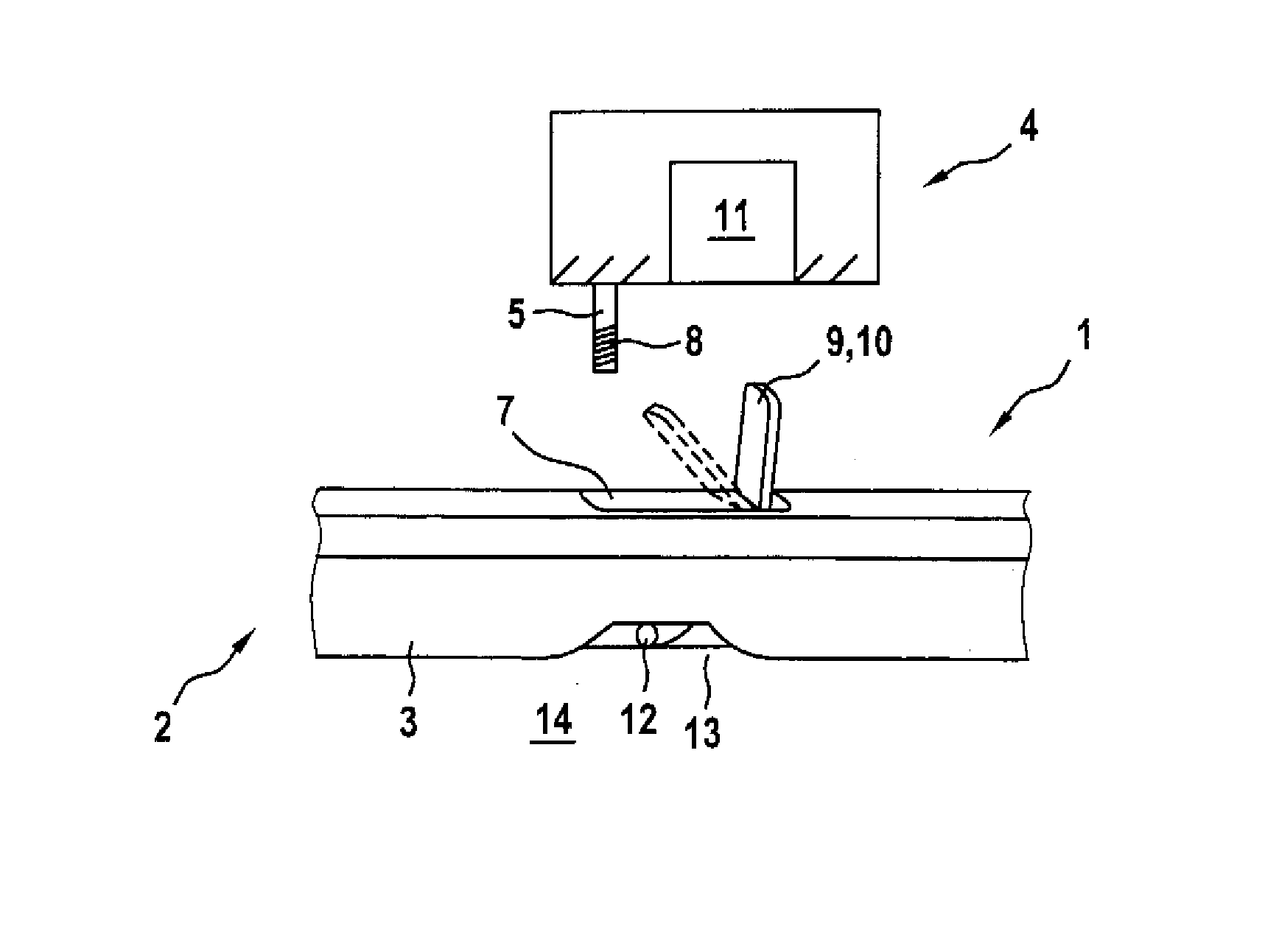
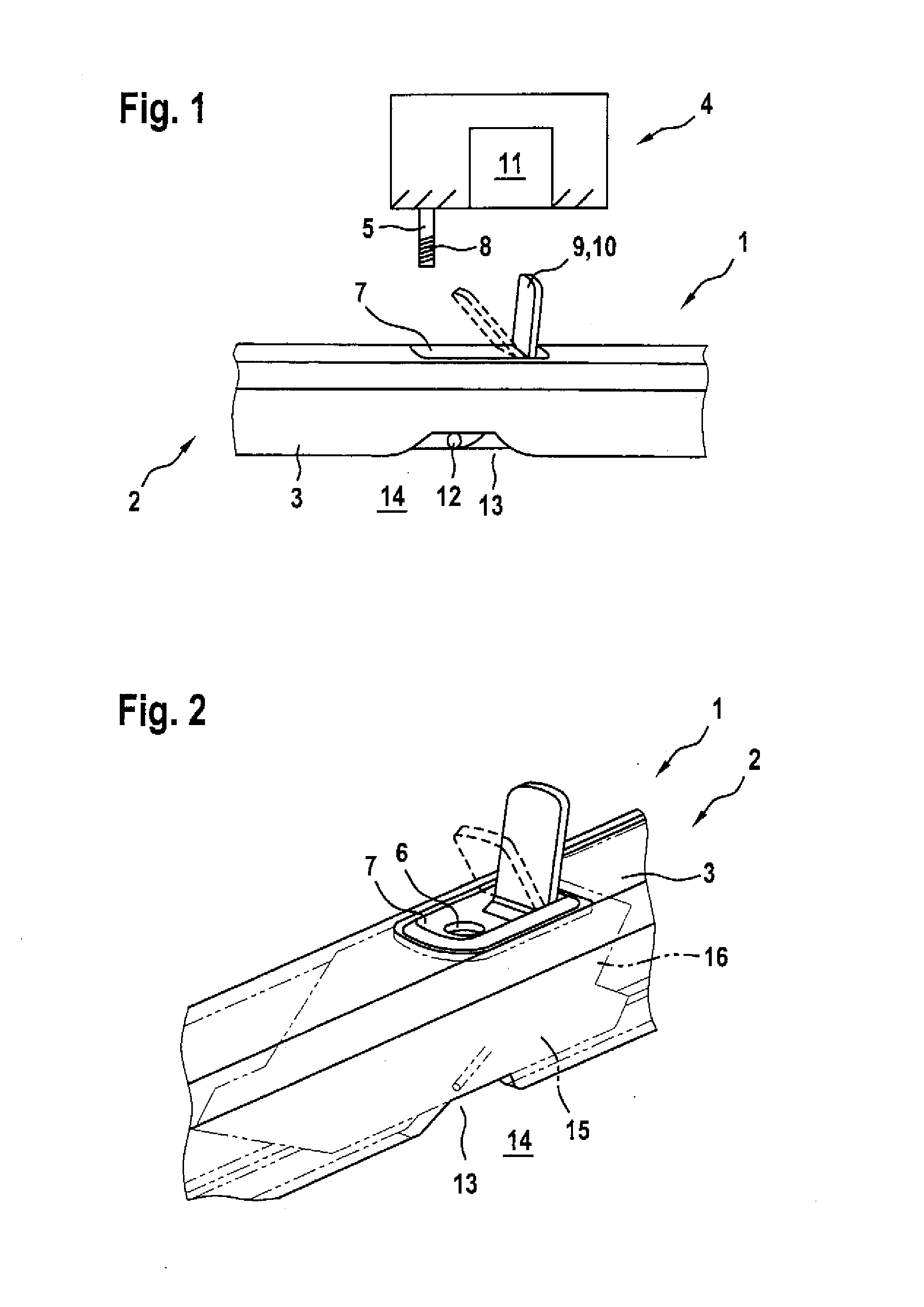
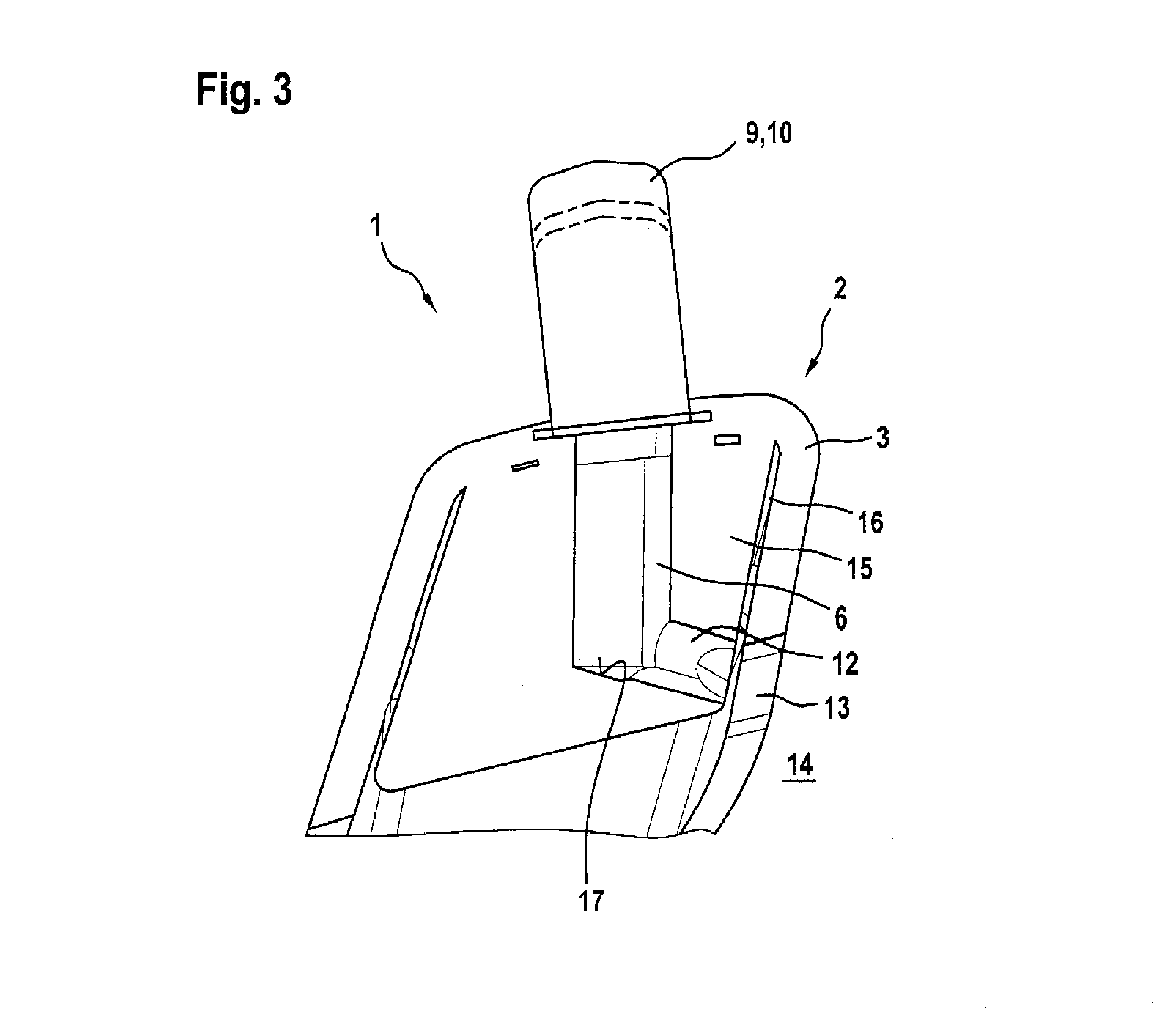
The present invention relates to a roof rack system for vehicles, which has a mounting receptacle located above the vehicle roof and a cover for closing a recess when the load carrier is not installed. The cover completely closes the recess. The system also has a drain line for removing moisture from the mounting receptacle to the surroundings of the roof rack. The drain line opens into a drain opening in the roof rails, which is formed by an open-edged recess of the roof rails on its side facing the vehicle roof. The technical effect of the invention is that the roof rack system always has a pleasing appearance, with no outlines of the cover when the load carrier is not installed, and the drain opening provides efficient moisture removal.

Problems solved by technology

However, commercially available load carriers can also be installed at locations where the switching device may be unable to detect the presence of the load carrier.
Alternatively, the load carrier may be unable to cooperate with the switching device, in particular when using a load carrier that is unauthorized for the motor vehicle.
Thus, there is a risk that the controller of the motor vehicle operates in the wrong mode when the load carrier or the entire roof rack assembly is improperly installed.

Method used


Image

  • Roof rack for a motor vehicle, and a method for operating a controller of a motor vehicle and a corresponding controller
  • Roof rack for a motor vehicle, and a method for operating a controller of a motor vehicle and a corresponding controller
  • Roof rack for a motor vehicle, and a method for operating a controller of a motor vehicle and a corresponding controller

Examples


first embodiment

[0042]FIG. 4 shows an area of the roof rack assembly 1 with a detection device 18 for detecting a cover state of the recess 7 in a The detection device 18 is composed of at least a magnet 19 and a magnetic field sensor 20. The latter may be, for example, a Hall sensor. The magnet 19 is disposed on the cover 9 or the flap 10, respectively, and can be displaced together with the cover / flap. Conversely, the magnetic field sensor 20 is stationary in the roof rails 2 and is advantageously located in the attachment element 15. The magnetic field sensor 20 is, for example, connected via a line 21 to a controller 22. The cover state of the recess 7 can be detected using the detection device 18. In the illustrated embodiment, the magnetic field generated by the magnet 19 is detected by the magnetic field sensor 20. When the cover 9 is closed, the magnet 19 is located closer to the magnetic sensor 20 than when the cover 9 has been opened or removed. Accordingly, the magnetic field detected w...

second embodiment

[0044]FIG. 5 shows an area of the roof rack assembly 1 with a detection device 18 in a This diagram shows again clearly that the flap 10 can be pivoted about a pivot axis 23 and has an actuation region 24 wherein the recess 7 is uncovered when the actuation region 24 is operated. Actuation occurs through application of a force in the direction of the arrow 25. The cover 9 and the flap 10, respectively, are again shown in two different positions, namely in a closed position (solid lines) and in an open position (dotted lines). The difference from the embodiment described with reference to FIG. 4 lies in the fact that both the magnet 19 and the magnetic field sensor 20 are arranged on the fastening element 15. Conversely, the cover 9 includes a magnetic yoke 26 used to transmit, when the cover 9 is in the closed position, a magnetic flux between the magnet 19 and the magnetic sensor 20. Conversely, when the cover 9 is removed or moved into the open position, the magnetic flux is at l...


PUM


Abstract

A roof rack assembly for a motor vehicle includes roof rails having a recess and constructed to be fastened on a vehicle roof of the motor vehicle. A load carrier to be installed on the roof rails has a mounting projection engaging with the roof rails through the recess when the load carrier is installed and cooperating with a mounting receptacle for retaining the load carrier. The recess is closed by a cover when the load carrier is not installed, with a detection device detecting a cover state of the recess. A method for operating a controller of a motor vehicle and a corresponding controller are also described.

Description

CROSS-REFERENCES TO RELATED APPLICATIONS[0001]This application claims the priority of German Patent Application, Serial No. 10 2012 014 696.5, filed Jul. 25, 2012, pursuant to 35 U.S.C. 119(a)-(d), the content of which is incorporated herein by reference in its entirety as if fully set forth herein.BACKGROUND OF THE INVENTION[0002]The present invention relates to a roof rack assembly for a motor vehicle, having roof rails that can be secured on the vehicle roof of the vehicle and a load carrier that can be mounted on the roof rails. The invention further relates to a method for operating a controller of a motor vehicle and to a corresponding controller.[0003]The following discussion of related art is provided to assist the reader in understanding the advantages of the invention, and is not to be construed as an admission that this related art is prior art to this invention.[0004]Roof racks of the aforementioned type are known in the art. They are composed of the roof rails, which ha...

Claims


Application Information

Patent Timeline
IPC IPC(8): B60R9/04B60R9/058
CPCB60R9/058B60R9/04
Inventor PFEIFFER, ULRICHBALLWEG, FELIXSCHMID, WOLFGANG
Owner AUDI AG
Learn More