Fabrication member

Active Publication Date: 2014-02-13
KRIP
View PDF4 Cites 1 Cited by
  • Summary
  • Abstract
  • Description
  • Claims
  • Application Information

AI Technical Summary

Benefits of technology

[0002]This invention relates to the manufacture of improved fabrication members, in particular, the manufac

Problems solved by technology

Such loads in vehicles may be exerted by the weight of the vehicle, by the cargo carried by the vehic

Method used


Image

  • Fabrication member
  • Fabrication member
  • Fabrication member

Examples


Example

DETAILED DESCRIPTION OF THE DRAWINGS

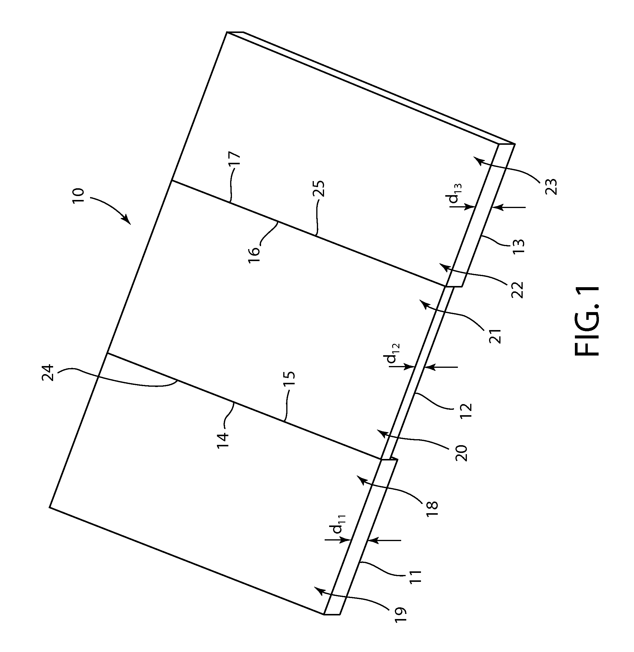
[0027]Referring to FIG. 1. Illustrated is a first planar member 11, second planar member 12, and third planar member 13. The first planar member 11 is provided having a desired cross-sectional shape and desired first set of mechanical properties suitable to form a first base of a composite structural fabrication member (see FIG. 2), having been uncoiled. The second planar member 12 is provided adjacent the first planar member 11, the first side 15 of the second planar member 12 abutting the first side 15 of the first planar member 11, the second planar member having been uncoiled. As used herein, adjacent includes touching and overlapping. For example a first planar member adjacent a second planar member includes the first and second planar members touching at side portions, and overlapping at side portions.

[0028]In alternative embodiments, the first side 15 of the second planar member 12 may extend over or under the first side 14 of the first pla...


PUM


Abstract

A method of making a composite fabrication member having a shape selected from the group consisting of C-shape, U-shape, or Z-shape by providing first and third planar members suitable to form bases of a composite fabrication member, providing a second planar member suitable to form a web of a composite fabrication member, uncoiling and passing through accumulators the planar members, aligning the planar members, attaching the first, second, and third planar members together at respective side portions by induction welding to form a composite intermediate product to form a composite fabrication member having a shape selected from the group consisting of C-shape, lipped C-shape, U-shape, lipped U-shape, Z-shape or lipped Z-shape.

Description

[0001]This application claims priority to U.S. provisional application No. 61 / 680,773 filed Aug. 8, 2012, the contents of which are hereby incorporated in their entirety.BACKGROUND AND SUMMARY[0002]This invention relates to the manufacture of improved fabrication members, in particular, the manufacturing of fabrication members having properties to create more effective and efficient fabrication members.[0003]Frame members, or fabrication members, are made from a variety of materials used for many different applications. Structural frame members, a subset of fabrication members, are used in applications where increased load is exerted in the structure. Such loads in buildings may comprise the gravitational load exerted by the weight of the building, the loads exerted by the manner in which the building is used, and loads exerted by the environment, such as from wind and seismic activity. Such loads in vehicles may be exerted by the weight of the vehicle, by the cargo carried by the v...

Claims


Application Information

Patent Timeline
IPC IPC(8): E04C3/04
CPCE04C3/04E04C3/07E04C2003/0413E04C2003/0473E04C2003/0482Y10T29/49627B21D51/02B21D47/04
Inventor SMITH, JEREMY RYANWHALEY, KENNON
Owner KRIP
Why Eureka
Try Eureka