Synchronous dc-dc conversion
a synchronous, dc-dc technology, applied in the direction of dc-dc conversion, power conversion system, climate sustainability, etc., can solve the problems of undesirable signal noise or additional efficiency loss, non-synchronous converter may operate in a low voltage, and achieve undesirable signal noise or additional loss
- Summary
- Abstract
- Description
- Claims
- Application Information
AI Technical Summary
Benefits of technology
Problems solved by technology
Method used
Image

Examples
example 1
Synchronous Buck Converter
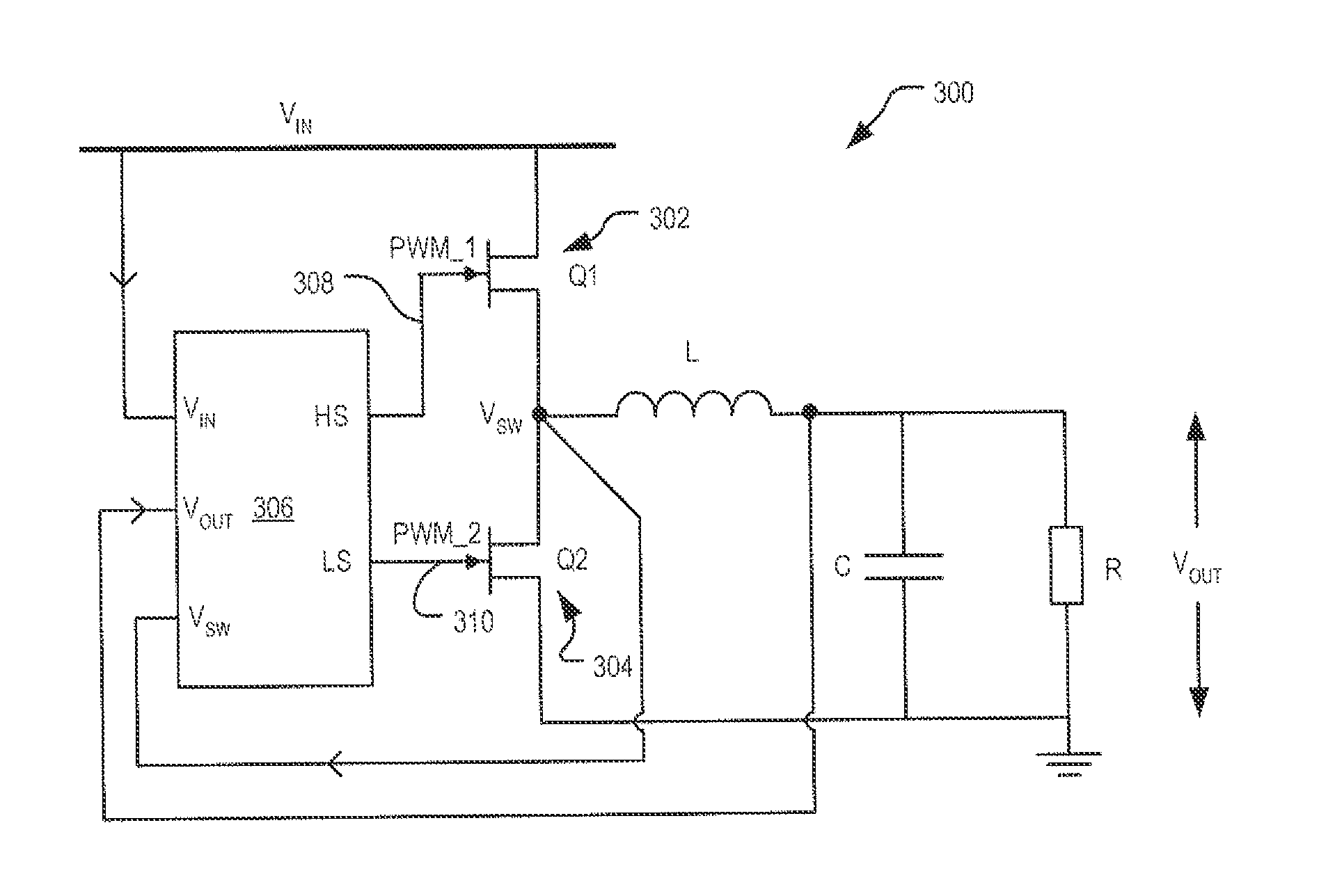
[0056]Referring initially to FIG. 3 there is shown a simplified schematic diagram of a synchronous DC-DC buck converter 300 according to an embodiment. As will be understood by a skilled reader, in operation a buck converter converts an input voltage (Vin) into an output voltage (Vout) less than the input voltage (Vin).
[0057]The illustrated converter 300 includes an active switch 302 (labelled as Q1), a synchronous rectifier 304 (labelled as Q2), and a controller 306. The active switch 302 and the synchronous rectifier 304 may include MOSFET devices having a low on-resistance (RDSON), a low gate charge, and suitable current and voltage ratings for the intended application. Selection of suitable MOSFET devices would be well within the knowledge of a person skilled in the art. The converter 300 also includes an inductor (L) and a capacitor (C) forming a circuit configuration for providing the output voltage (Vout) to a load (R). The function and selection of ...
example 2
Synchronous Boost Converter
[0094]Referring now to FIG. 9 there is shown a simplified schematic diagram of a synchronous DC-DC boost converter 900 according to an embodiment. As will be appreciated, a boost converter accepts an input voltage (Vin) and produces an output voltage (Vout) higher than the input voltage.
[0095]The converter 900 includes an active switch (labelled as Q1), a synchronous rectifier (labelled as Q2), and a controller 306. The controller 306, active switch Q1 and the synchronous rectifier Q2 are of the same type as the corresponding elements described above in relation to Example 1.
[0096]The operation of the converter 900 is similar in principle to the converter 300 described with reference to Example 1 in that it involves controlling the active switch Q1 using a first gate signal (PWM_1) and controlling the synchronous rectifier Q2 using a second gate signal (PWM_2). In the case of the boost converter 900, however, when the active switch Q1 is turned on by PWM_1...
PUM
 Abstract
Description
Claims
Application Information
 - R&D Engineer
- R&D Manager
- IP Professional
- Industry Leading Data Capabilities
- Powerful AI technology
- Patent DNA Extraction
Browse by: Latest US Patents, China's latest patents, Technical Efficacy Thesaurus, Application Domain, Technology Topic.
© 2024 PatSnap. All rights reserved.Legal|Privacy policy|Modern Slavery Act Transparency Statement|Sitemap