Liquid discharge head and liquid discharge apparatus
a liquid discharge head and liquid discharge technology, applied in printing and other directions, can solve the problems of long waiting time until the apparatus becomes available for printing at the beginning of use, the inability to adapt well to the inner wall of the ink, and the risk of printing failure, etc., to achieve the effect of suppressing the generation of air bubbles
- Summary
- Abstract
- Description
- Claims
- Application Information
AI Technical Summary
Benefits of technology
Problems solved by technology
Method used
Image

Examples
first embodiment
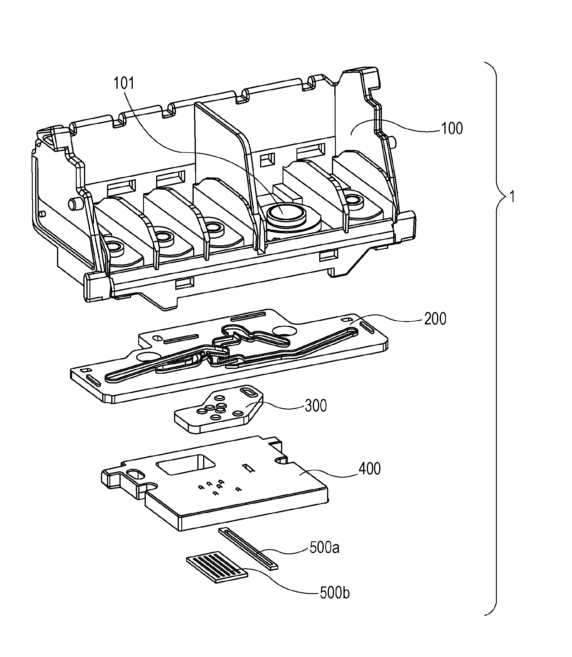
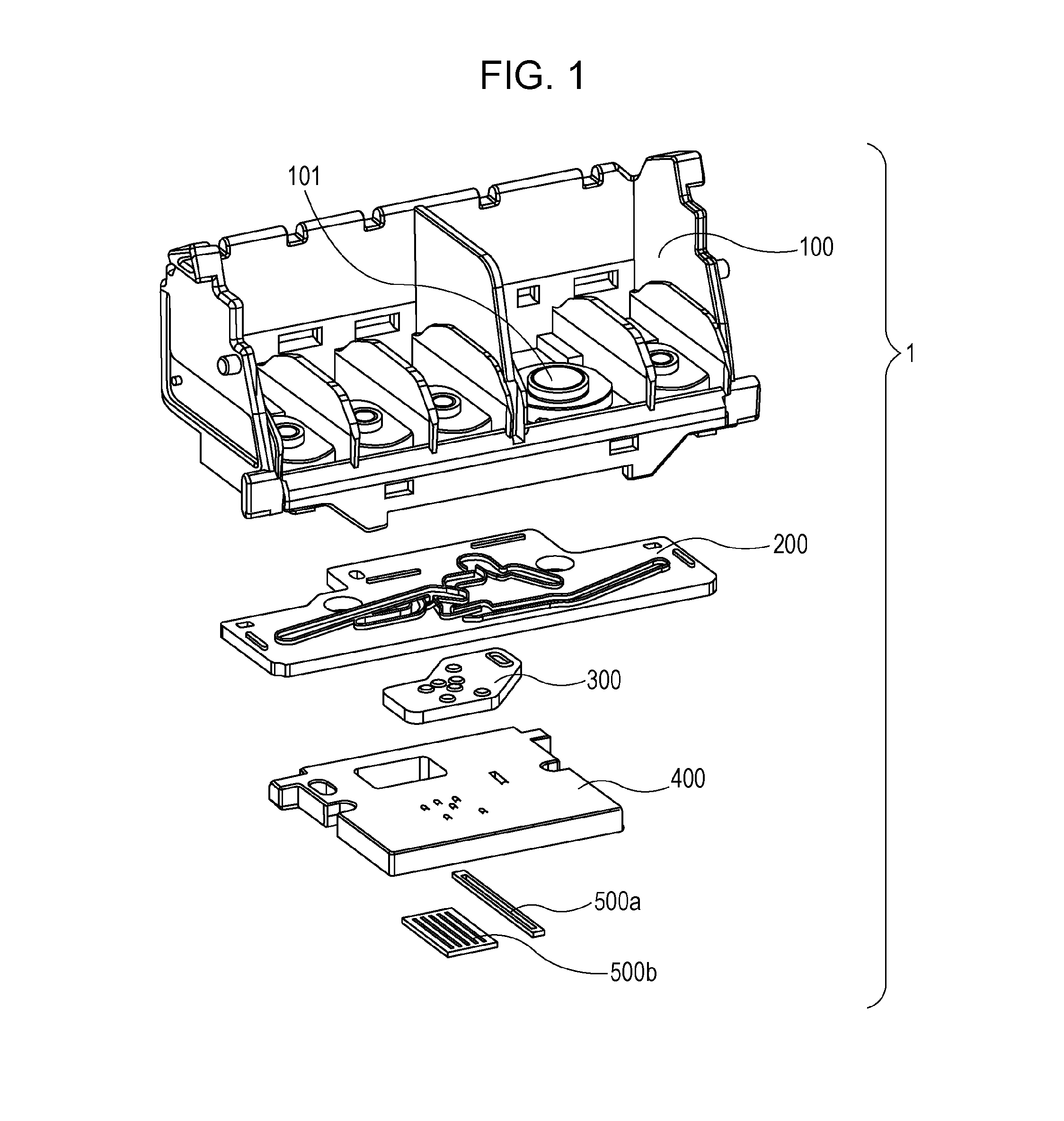
[0026]FIG. 1 is an exploded perspective view of an ink jet recording head 1 as a liquid discharge head. The ink jet recording head 1 according to a first embodiment includes recording element rows for pigment black ink and four colors of dye ink, and flow channels for supplying ink from ink tanks (not illustrated) for storing ink for the respective recording element rows.
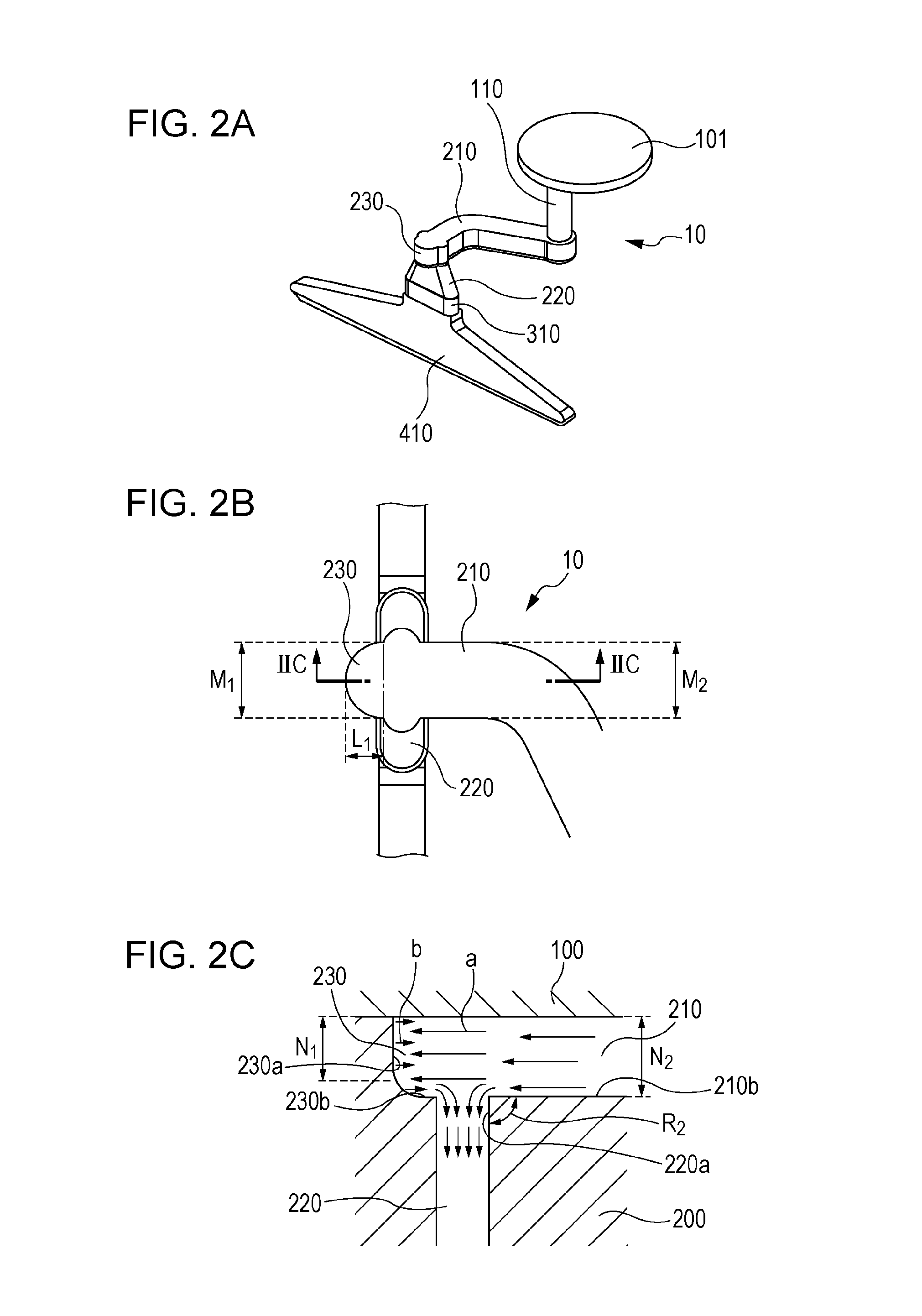
[0027]A flow channel 10 for pigment black ink from among a plurality of flow channels will be illustrated in FIGS. 2A to 2C. FIG. 2A is a schematic perspective view for explaining the shape of the flow channel 10, FIG. 2B is a top view illustrating part of the flow channel 10, and FIG. 2C is a cross-sectional view taken along the line IIC-IIC in FIG. 2B. FIGS. 2A and 2B illustrate inner walls which define the flow channel 10, and FIG. 2C illustrates part of a first flow channel forming member 100 and part of a second flow channel forming member 200 described later in addition to the flow channel 10.
[0028]As illustra...
second embodiment
[0048]Subsequently, a second embodiment will be described. FIGS. 4A to 4C illustrate the flow channel 10 for pigment black ink of the second embodiment. FIG. 4A is a schematic perspective view for explaining the shape of the flow channel 10, FIG. 4B is a top view illustrating part of the flow channel 10, and FIG. 4C is a cross-sectional view taken along the line IVC-IVC.
[0049]The position of the bottom surface 230b of the third flow channel portion 230 (FIG. 4C) in the second embodiment is different from the first embodiment. However, the basic configuration is the same as that of the first embodiment.
[0050]In the second embodiment, the dimensional relationship between a height N3 of the third flow channel portion 230 and the height N2 of the first flow channel portion 210 at a connecting portion with respect to the first flow channel portion 210 in order to further restrain the generation of the air bubble at the time of initial filling is set to N23. Upper surfaces of the first fl...
third embodiment
[0055]Subsequently, a third embodiment will be described with reference to FIGS. 6A to 8D.
[0056]FIGS. 6A to 6C illustrate part of the flow channel 10 for pigment black ink of the third embodiment. FIGS. 6A and 6B are schematic perspective views and FIG. 6C is a side view.
[0057]As illustrated in FIG. 6C, the third embodiment is different from the first and second embodiments in that the bottom surface 230b (the second wall) of the third flow channel portion 230 in the third embodiment is an inclined surface. However, the basic configuration is the same as that of the first and second embodiments.
[0058]FIGS. 8A to 8D are drawings illustrating a state in which ink I flows in the flow channel 10 of the third embodiment. In the same manner as the first and second embodiments, the ink supplied through the first flow channel portion 210 enters the third flow channel portion 230, and interflows with ink reversed by the wall 230a of the third flow channel portion 230. Accordingly, kinetic en...
PUM
 Abstract
Description
Claims
Application Information
 - R&D
- Intellectual Property
- Life Sciences
- Materials
- Tech Scout
- Unparalleled Data Quality
- Higher Quality Content
- 60% Fewer Hallucinations
Browse by: Latest US Patents, China's latest patents, Technical Efficacy Thesaurus, Application Domain, Technology Topic, Popular Technical Reports.
© 2025 PatSnap. All rights reserved.Legal|Privacy policy|Modern Slavery Act Transparency Statement|Sitemap|About US| Contact US: help@patsnap.com