
Manufacturing method and manufacturing apparatus for fuel cell unit

a manufacturing apparatus and fuel cell technology, applied in the direction of final product manufacturing, sustainable manufacturing/processing, electrochemical generators, etc., can solve the problems and affecting the efficiency of the fuel cell unit. , to achieve the effect of reducing the amount of use of a relatively expensive electrolyte membrane material, reducing the surface size of the electrolyte membran

Active Publication Date: 2022-02-10
HONDA MOTOR CO LTD
View PDF8 Cites 0 Cited by
  • Summary
  • Abstract
  • Description
  • Claims
  • Application Information

AI Technical Summary

Benefits of technology

The present invention is about a way to accurately position and reduce the likelihood of displacement between a resin frame equipped membrane electrode assembly and a separator in a battery assembly. This is accomplished by using a positioning convex portion on the separator and a resin frame equipped membrane electrode assembly. By providing a resin frame member on the outer periphery of the membrane electrode assembly, the strength of the electrolyte membrane can be protected, and the size of the membrane can be reduced. However, there is a concern of positional deviation between the resin frame equipped membrane electrode assembly and the separator due to the warping of the resin frame member. The invention proposes a solution to this problem by allowing the resin frame member to conduct heat to the metal spacer during laser irradiation, resulting in a uniform weld and a desired shape of the joining target portion with suppressed air bubbles and excellent joint strength. Overall, this invention enables accurate positioning and reliable joining of the battery assembly components.

Problems solved by technology

In such an electrolyte membrane, the strength is likely to decrease by thinning.
However, the resin frame member is likely to warp.
Therefore, as described above, even in the configuration in which the resin frame equipped membrane electrode assembly is engaged with the positioning convex portion of the separator, there is a concern that positional deviation occurs between the resin frame equipped membrane electrode assembly and the separator.

Method used


Image

  • Manufacturing method and manufacturing  apparatus for fuel cell unit
  • Manufacturing method and manufacturing  apparatus for fuel cell unit
  • Manufacturing method and manufacturing  apparatus for fuel cell unit

Examples


Embodiment Construction

[0025]In the following drawings, components having the same or similar functions and effects are denoted by the same reference numerals, and repeated description thereof may be omitted.

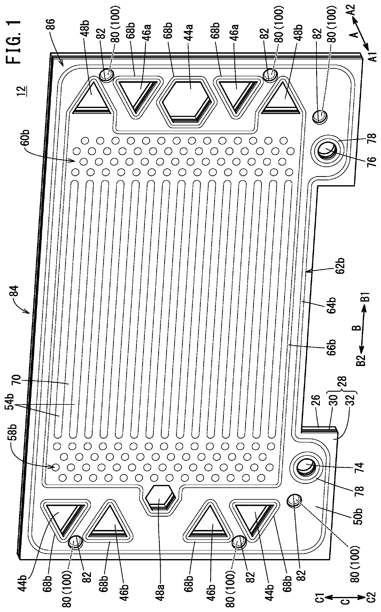
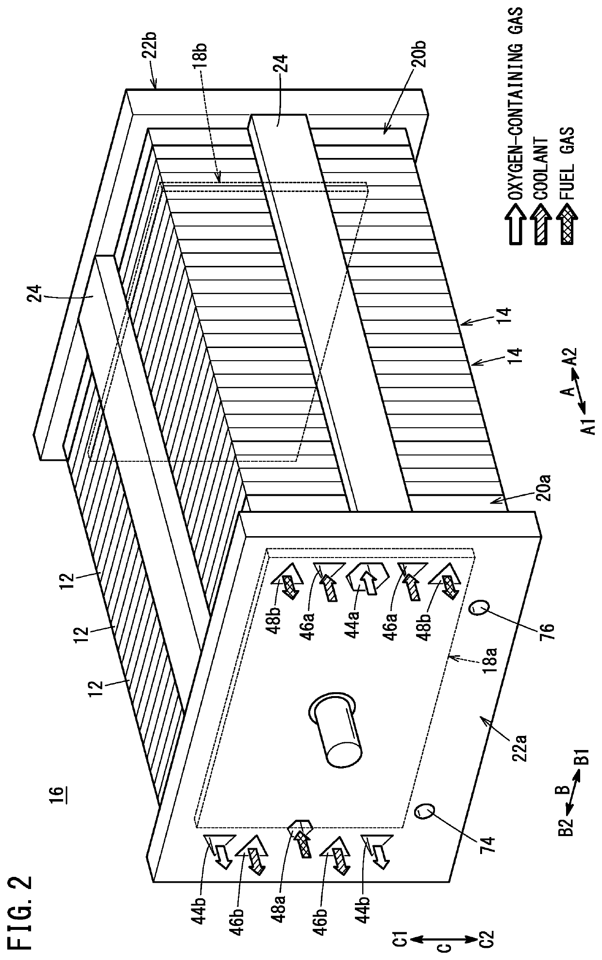
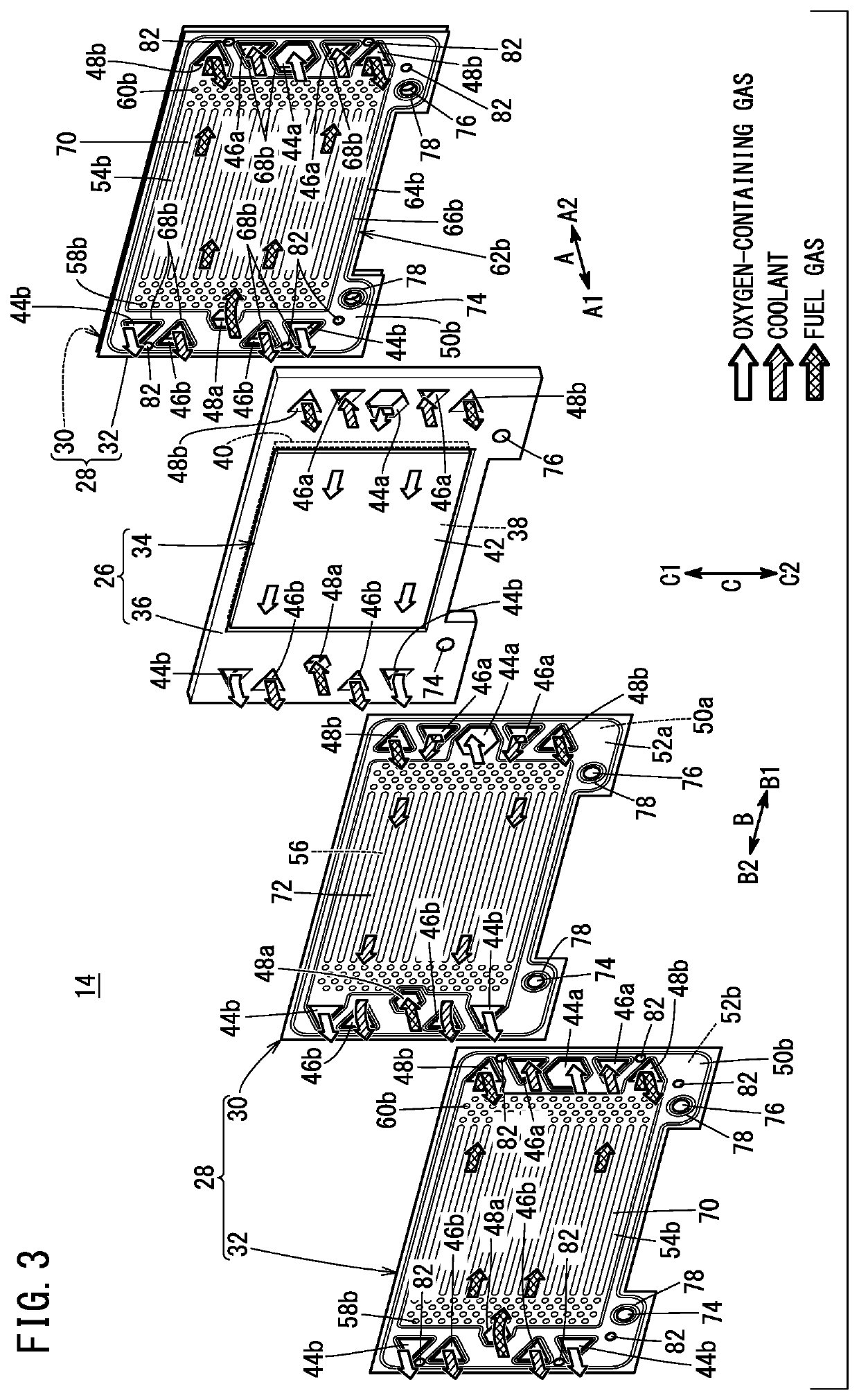
[0026]A plurality of fuel cell units 12 (FIG. 1) obtained by applying the manufacturing method and manufacturing apparatus 10 (FIG. 8) for a fuel cell unit according to the present embodiment can be stacked to form the power generation cell 14 shown in FIGS. 2 and 3. The plurality of power generation cells 14 are stacked in the horizontal direction (direction of arrow A) or the vertical direction (direction of arrow C) to form the fuel cell stack 16 of FIG. 2. The fuel cell stack 16 is mounted on a fuel cell vehicle such as a fuel cell electric vehicle (not shown).

[0027]As shown in FIG. 2, a terminal plate 18a, an insulator 20a, and an end plate 22a are disposed toward the outside in this order at one end portion (end portion in the arrow A1 direction) in the stacking direction (arrow A direction) of ...


PUM


Abstract

The manufacturing method for the fuel cell unit includes a stacking step and a laser irradiation step. In the stacking step, a stacked portion including, stacked together, a resin frame member of a resin frame equipped membrane electrode assembly and an outer peripheral portion of a separator is placed on a metal spacer. The resin frame member at a joining target portion of the stacked portion is placed so as to face a recess of the metal spacer. In the laser irradiation step, the separator at the joining target portion in a state where the resin frame member faces the recess is irradiated with a laser beam to thereby form a welded portion where the resin frame member and the separator are welded to each other.

Description

CROSS-REFERENCE TO RELATED APPLICATION[0001]This application is based upon and claims the benefit of priority from Japanese Patent Application No. 2020-134303 filed on Aug. 7, 2020, the contents of which are incorporated herein by reference.BACKGROUND OF THE INVENTIONField of the Invention[0002]The present invention relates to a manufacturing method and a manufacturing apparatus for a fuel cell unit.Description of the Related Art[0003]For example, a polymer electrolyte fuel cell includes a membrane electrode assembly (MEA). The membrane electrode assembly includes an electrolyte membrane made of a polymer ion exchange membrane. An anode electrode is disposed on one surface of the electrolyte membrane. A cathode electrode is disposed on the other surface of the electrolyte membrane. A power generation cell (unit cell) is formed by sandwiching the membrane electrode assembly between separators. The fuel cell is used as, for example, an in-vehicle fuel cell stack. The fuel cell stack i...

Claims


Application Information

Patent Timeline
IPC IPC(8): H01M8/0297H01M8/1004
CPCH01M8/0297H01M2008/1095H01M8/1004B29C65/02H01M8/0273H01M8/0284H01M8/242Y02E60/50Y02P70/50H01M2250/20
Inventor WADA, YUSUKESUMI, SHINTARO
Owner HONDA MOTOR CO LTD
Learn More