A silent gear pump or motor suppressing troubles of trapping fluid

a gear pump or motor technology, applied in the direction of liquid fuel engines, machines/engines, rotary/oscillating piston pump components, etc., can solve the problems of high hertz pressure pulse, restricted use in quiet environment equipment, severe noise and cavitation, etc., to prevent sudden pressure drop in the loaded chamber, eliminate teeth bouncing contact, and high

Active Publication Date: 2016-04-21
LIM NAG BOK
View PDF1 Cites 1 Cited by
  • Summary
  • Abstract
  • Description
  • Claims
  • Application Information

AI Technical Summary

Benefits of technology

[0015]at least an elastic disc capsule contained in a compensating chamber having compressible gas therein, which has strength enabling to save a space for absorbing the squeezed fluid against a pressure therein for sealing off the trapped interstice during a beginning moment of the decreasing trap interstice; and
[0017]Whereby, at the beginning moment of the decreasing trap interstice of the meshing gear, the trapped interstice are sealed off inwardly or outwardly by the fluid-leak-tight backlash and the closed opening of the passage, which forms a pressure buffer zone between the loaded chamber and the compensation chamber, so that the elastic disc capsule is protected from being collapsed by the pressure transmission from the high pressure chamber to the compensating chamber via the trapped interstice, and also sudden pressure drop in the loaded chamber is prevented. And upon further rotation of the gear, the decreasing trap interstice starts to communicate with the compensating chamber and the excessive volume of the trapped fluid therein is absorbed by the reduced space of the elastic disc capsules responding to the trap cycles in extremely high frequency, wherein the presetting of the operating pressure in the compensating chamber against the strength of the deflection of the elastic disc capsule is possible so that high pressure ripple therein and the disengagement of the teeth are prevented, eliminating teeth bouncing contact. And upon further rotation of the gears, the volume of the trapped interstice becomes its minimum at the theoretical plane including the centers of the support shafts of the gears, thereafter the volume of the trapped interstice increase creating a vacuum pressure wherein the increased space is filled up with the fluid repelled from the compensating chamber through the communication passage by the pressure difference between the elastic disc capsule and the increasing trap interstice, suppressing air bubble generation. Whereby the variation of the volume trapped in the interstice of meshed gears is compensated by the elastic disc capsule without undesirable loss of high pressure fluid in the discharge chamber, which is enable to suppress pressure pulse, cavitation, teeth bouncing contact, achieving low noise, low vibration and high efficiency gear pump or motor or gear refrigerating compressor.

Problems solved by technology

However, in spite of the merits as such, the high noise and aeration due to meshing external gears has restricted the employments in a quiet environment equipments such as pumps or motors or refrigerating compressors for electric motor vehicles or room services or in a large delivery volume application.
During the normal operation of a fluid delivery device in the prior art, the teeth of the meshed gears create interstices between the root curves and the mating tooth tips respectively of which volume decreases until it reaches at the theoretical plane including the centers of the support shafts of the gears and increases thereafter during the tooth contact moves along the line of action, wherein trapped fluid still create high pressure ripples during the decreasing process and aeration during increasing process, causing severe noise and cavitation, which is known as trapping phenomenon.
It is known that the troubles due to the aforesaid trapping phenomenon comes from which the incompressible fluid confined in a variable volume of a rigid interstice during the rotation of the gear's, wherein the pressure variation has inevitably mutual affection with inlet and outlet chamber by the pressure transmission or fluid leakage inwardly or outwardly through the clearances surrounding the trapped interstice, such as gear backlash and the clearances along the side face of gears, which invites pressure ups not only in the trapped interstice, but also in the high pressure chamber, creating pressure pulse in high hertz.
And some approaches of the prior art to solve the aforesaid problems, which provide passages to relieve the pressure in the trap region through a passage communicating either to the inlet or outlet chamber, revealed a sudden pressure drop in the high pressure chamber and fluid leakage into trap chamber and losing volumetric efficiency, or higher pressure pulse due to direct transmission of the decreased volume in to high pressure chamber.

Method used


Image

  • A silent gear pump or motor suppressing troubles of trapping fluid
  • A silent gear pump or motor suppressing troubles of trapping fluid
  • A silent gear pump or motor suppressing troubles of trapping fluid

Examples


Embodiment Construction

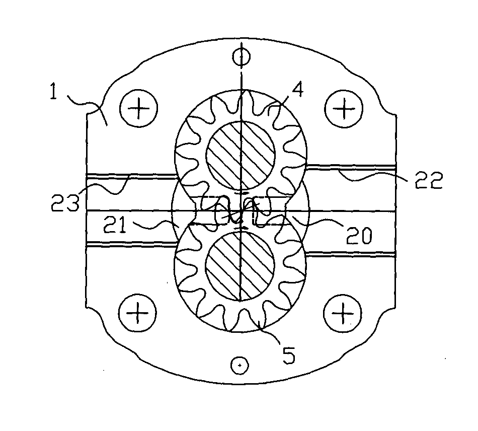
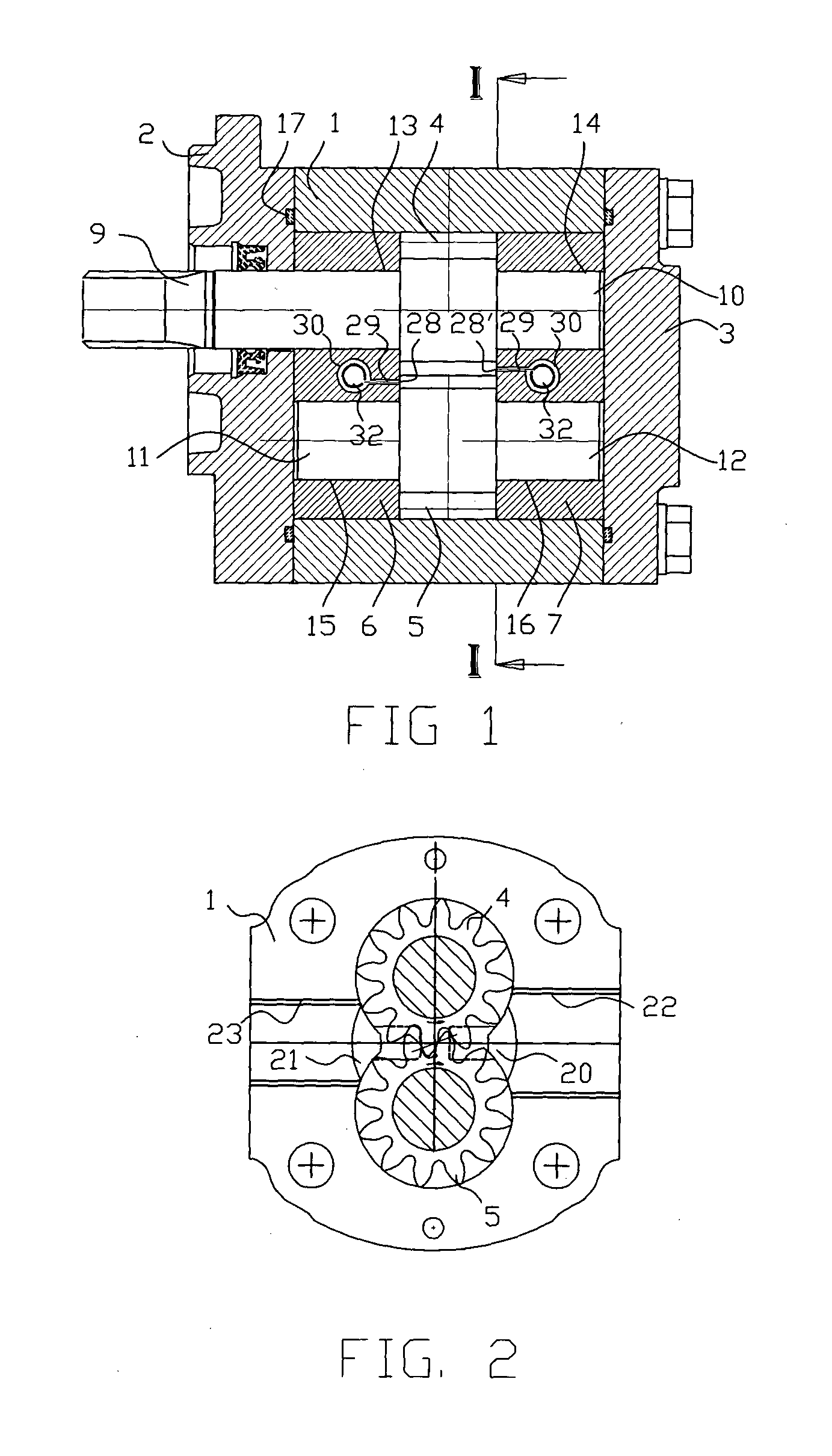
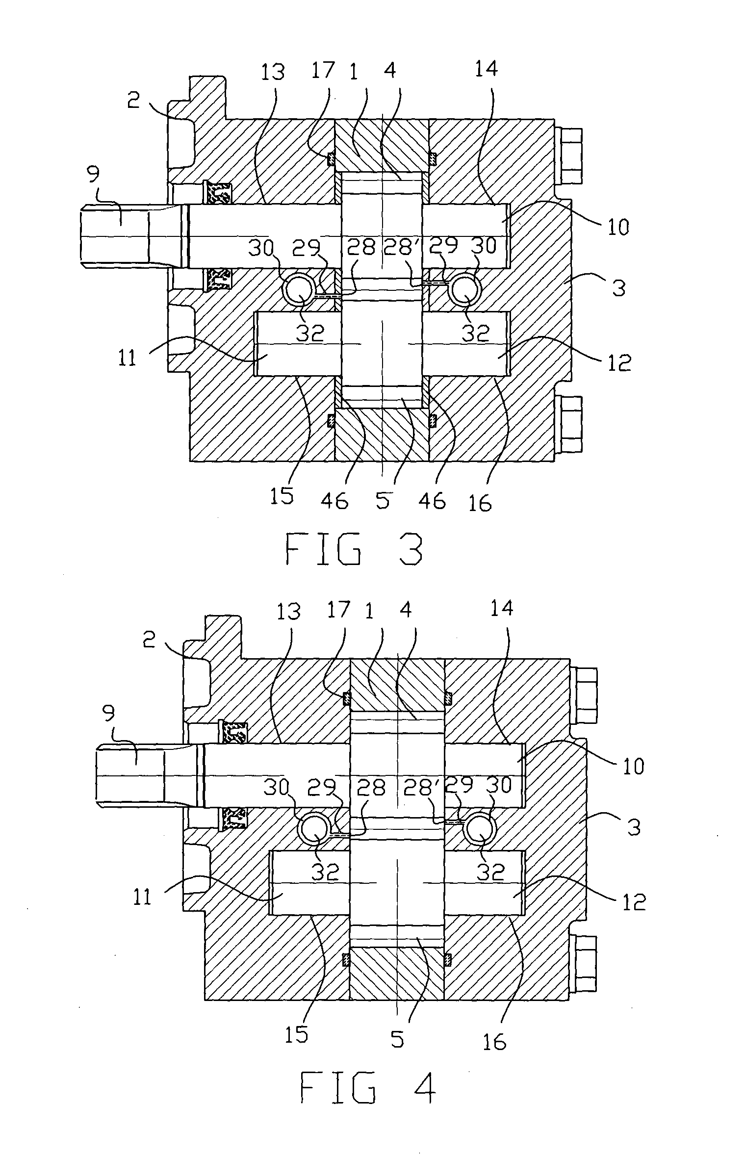
[0033]Referring now to the drawings in detail and initially to FIG. 1 and 2, there is shown one embodiment of a gear pump or motor, or a gear refrigerating compressor, according to the present invention. Therein a central housingl provides two intersecting bores for a gear chamber, having a cross section substantially in the form of a peanut. The gear chamber contains a pair of meshed external gears 4 and 5 having supporting shaft 9, 10, 11 and 12, of which ends are closed by opposite bearing blocks 6 and 7. The housing end plates 2 and 3 are fixed thereto by screws as illustrated in the embodiment. The shafts 9, 10, 11 and 12 of the gears are mounted in rotatable way at bearing bores 13, 14, 15 and 16 in the bearing blocks 6 and 7. The shaft 9 extends through the bearing block 6 to the outside of the end plate 2, for jointing with a prime mover (not illustrated) to rotate the gear 4 serving as a shaft gear and the gear 5 serving as a driven gear.

[0034]The fluid-leak-tight backlash ...


PUM


Abstract

Fluid delivery devices using a pair of meshed external gears, in spite of no reciprocating component for fluid delivery enabling low rotational vibration, the high noise due to the trapping phenomenon, and the teeth bouncing contact due to undesired large backlash heretofore afforded in the gear manufacturing process, restrict the employments in the industrial field requiring quiet environment such as electric motor vehicles or room services.Accordingly, a gear pump or motor or a gear refrigerating compressor comprising a shaft gear and a driven gear meshed rotatably within a gear chamber formed with a housing and opposite side walls, which delivers fluids from a inlet chamber to a outlet chamber; a backlash of the meshed gears having fluid-leak-tight clearance; a closed chamber provided in a internal portion of at least a side wall; an opening provided on a side wall from which a communication passage extends to a closed chamber; and at least a elastic disc capsule contained in the closed chamber, comprising a pair of concaved elastic disc plate abutted and sealed against each other with gas inside, of which occupying volume varies elastically subject to the fluid pressure therein enabling to absorb or expel the squeezed fluid in the trapped interstice during the trapping period of the interstice, whereby the fluid entrapped in the interstices isolated by the fluid-leak-tight backlash suppressing the pressure transmission inwardly or outwardly, whereof volumetric variation during the trapping period is compensated by the compression or expansion of the elastic disc capsule, suppressing pressure pulse and air bubble generation and eliminating the teeth bouncing contact, achieving a low noise, low vibration and high efficiency gear pump or motor or refrigerating compressor.

Description

RELATED APPLICATIONS[0001]This application claims that the benefit of the P.C.T. Application No. PCT / KR2013 / 003226 filed 17 Apr. 2013, which is hereby incorporated herein by reference.FIELD OF THE INVENTION[0002]The present invention relates generally to a fluid delivery device comprising a pair of meshed external gears. More particularly it relates to a gear pump or motor, or a gear refrigerating compressor, having a pair of external gears rotatably mounted in a gear chamber.BACKGROUND OF THE INVENTION[0003]Fluid delivery devices using a pair of meshed external gears, which are unique in a rotational construction using no reciprocating component for fluid delivery enabling low rotational vibration, have a high power density in a simple and economic construction so that various applications are made in the industrial fields such as pumps or motors. However, in spite of the merits as such, the high noise and aeration due to meshing external gears has restricted the employments in a q...

Claims


Application Information

Patent Timeline
Patent Type & Authority Applications(United States)
IPC IPC(8): F01C5/06F04C27/00F04C28/18F01C21/00F01C19/02F01C19/06F01C19/08F01C20/18F04C18/18F01C1/18
CPCF01C5/06F04C18/18F04C27/003F04C27/006F04C27/004F04C28/18F01C21/005F01C19/025F01C19/06F01C19/085F01C20/18F01C21/006F01C1/18F01C1/088F01C21/108F04C18/088F04C29/0035F04C2230/602F04C2270/135
Inventor LIM, NAG-BOK
Owner LIM NAG BOK
Why Eureka
Try Eureka