Portable electronic device

a technology of electronic devices and portable devices, which is applied in the direction of portable computers, instruments, and electric apparatus casings/cabinets/drawers, etc., can solve the problems of inconvenience for users, tablet computers and keyboard modules are easily separated from each other, and the thickness reduction of notebook computers is limited. , to achieve the effect of improving magnetic absorption strength and binding stability

Active Publication Date: 2014-02-13
WISTRON CORP
View PDF62 Cites 36 Cited by
  • Summary
  • Abstract
  • Description
  • Claims
  • Application Information

AI Technical Summary

Benefits of technology

[0010]Therefore, in the present invention the second fixed magnetic part on the second case attracts the movable magnetic part in the first case, so that the second fixed magnetic part and the movable magnetic part are directly magnetically absorbed together, so as to improve magnetic absorption strength and binding stability between the first case and the second case. In the following, implementation manners of the present invention are further described with embodiments and drawings.

Problems solved by technology

A light, thin, short, and small notebook computer is commercially available, but since a keyboard module is still of a certain thickness, further reduction of the thickness of the notebook computer is limited.
However, when many characters must be typed, the tablet computer without a keyboard module still causes inconvenience to a user.
However, the binding strength of the tablet computer and the keyboard module is often insufficient, resulting in a situation that the tablet computer and the keyboard module are easily separated from each other.

Method used


Image

  • Portable electronic device
  • Portable electronic device
  • Portable electronic device

Examples


Embodiment Construction

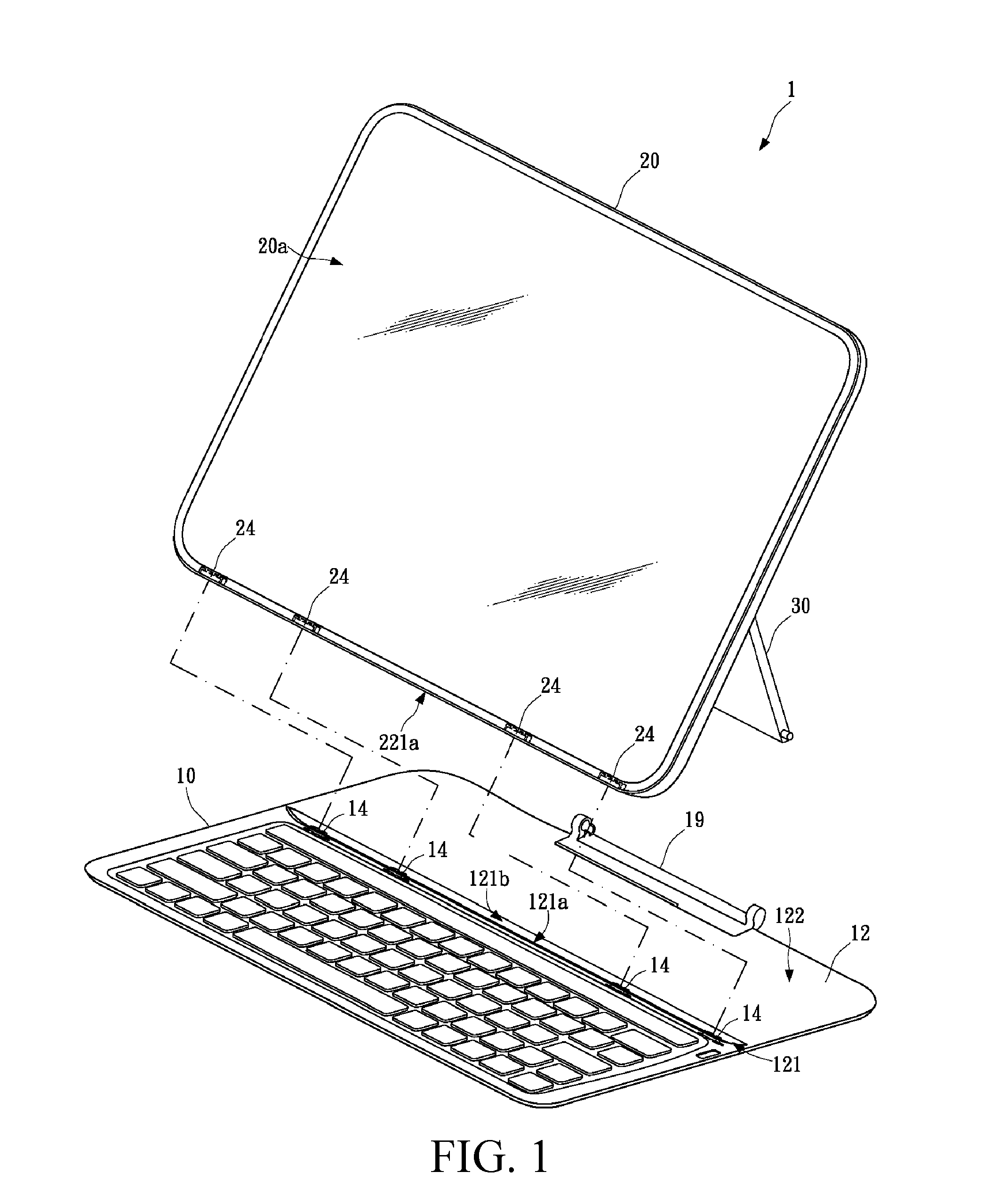
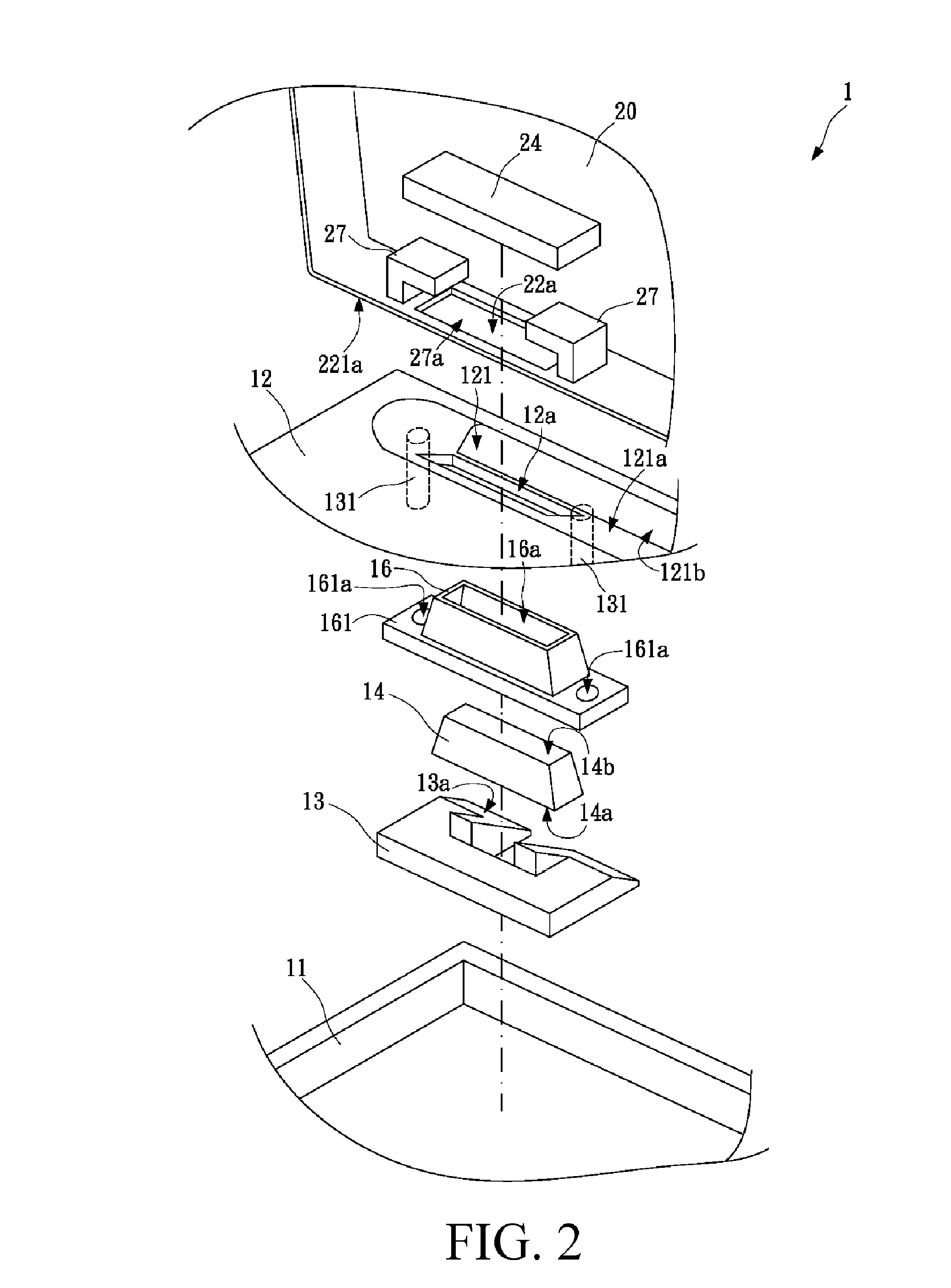
[0021]FIG. 1 is a three-dimensional view of a specific embodiment of the present invention and FIG. 2 is a schematic partially exploded view of a specific embodiment of the present invention. Please refer to FIG. 1 and FIG. 2, in which a portable electronic device 1 is disclosed. The portable electronic device 1 of this embodiment includes a first case 10, a first fixed magnetic part 13, a movable magnetic part 14, a second case 20, and a second fixed magnetic part 24.

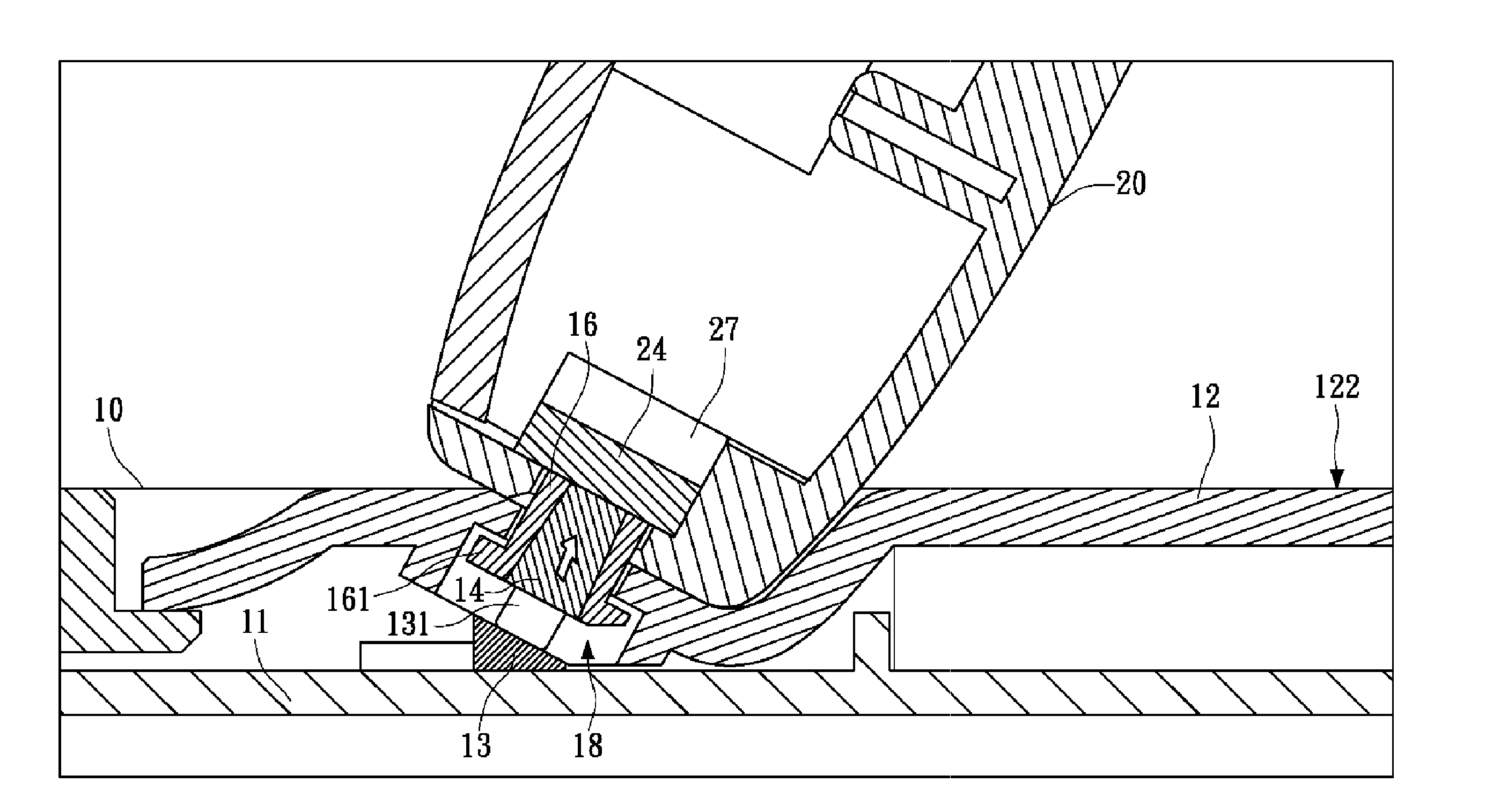
[0022]The first case 10 has a bottom plate 11 and a top plate 12 corresponding to each other with an interval from top to down. The top plate 12 preferably has a positioning recess 121 at a proper place. In this embodiment, the positioning recess 121 is a recessed structure with a V-shaped cross section and is formed with a first engagement surface 121a and a holding surface 121b opposite to each other. A positioning space is formed between the first engagement surface 121a and the holding surface 121b opposite to each...


PUM


Abstract

Provided is a portable electronic device, including a first case, a first fixed magnetic part, a movable magnetic part, a second case, and a second fixed magnetic part. The first case has a bottom plate and a first engagement surface, and an angle is formed between the bottom plate and the first engagement surface. The first fixed magnetic part is disposed on the bottom plate, and the first fixed magnetic part and the first engagement surface form an accommodating space. The movable magnetic part is movably disposed in the accommodating space. The second case is rotatably connected to the first case and has a second engagement surface. The second fixed magnetic part is disposed at the second engagement surface. When the second engagement surface is held to the first engagement surface, the movable magnetic part is attracted by the second fixed magnetic part and adsorbed to it.

Description

CROSS-REFERENCES TO RELATED APPLICATIONS[0001]This non-provisional application claims priority under 35 U.S.C. §119(a) on Patent Application No. 101128680 filed in Taiwan, R.O.C. on 2012, Aug. 8, the entire contents of which are hereby incorporated by reference.BACKGROUND OF THE INVENTION[0002]1. Technical Field[0003]The present invention is a portable electronic device, and is particularly a portable electronic device having a magnetic element.[0004]2. Related Art[0005]Due to the popularization of mobile networks, the features required by consumers of portable electronic devices are becoming increasingly improved. A light, thin, short, and small notebook computer is commercially available, but since a keyboard module is still of a certain thickness, further reduction of the thickness of the notebook computer is limited.[0006]Since touch technology continues to advance and network browsing and search operations do not of the require the typing of many characters for an extended dura...

Claims


Application Information

Patent Timeline
Patent Type & Authority Applications(United States)
IPC IPC(8): G06F1/16
CPCG06F1/1669G06F1/1626G06F1/1632G06F3/0202G06F1/1613
Inventor LIANG, CHEN-YI
Owner WISTRON CORP
Why Eureka
Try Eureka