Multi-rack, door-mounted heat exchanger

a heat exchanger and multi-rack technology, applied in lighting and heating apparatus, cooling/ventilation/heating modifications, metal-working apparatus, etc., can solve problems such as difficult approach and difficulty in cooling, and achieve the effect of facilitating ingress and egress of external air, facilitating the definition of a common airflow plenum, and facilitating holding

Active Publication Date: 2014-02-13
LENOVO GLOBAL TECH INT LTD
View PDF12 Cites 0 Cited by
  • Summary
  • Abstract
  • Description
  • Claims
  • Application Information

AI Technical Summary

Benefits of technology

[0005]The shortcomings of the prior art are overcome and additional advantages are provided through the provision of an air-cooling apparatus for facilitating cooling of airflow passing through multiple electronics racks. The apparatus includes a securing mechanism for holding at least two separate electronics racks in fixed relation adjacent to each other, and a multi-rack door sized and configured to span one of the air inlet sides or the air outlet sides of the at least two separate electronics racks held by the securing mechanism in fixed relation. The two separate electronics racks are at least partially air-cooled, and each has an air inlet side and an air outlet side. The securing mechanism holds the at least two separate electronics racks in fixed relation adjacent to each other with the air inlet sides facing a first direction, and the air outlet sides facing a second direction. The multi-rack door includes a door frame with an airflow opening, and an air-to-liquid heat exchanger supported by the door frame. The airflow opening of the door frame facilitates the ingress and egress of external air through the two at least separate electronics racks, and the air-to-liquid heat exchanger is disposed so that airflow through the airflow opening passes across the air-to-liquid heat exchanger. The air-to-liquid heat exchanger extracts heat from the air passing thereacross, and air passing through the one of the air inlet sides or the air outlet sides of the at least two separate electronics racks passes across the air-to-liquid heat exchanger. A first electronics rack of the at least two separate electronics racks has a shorter depth than a second electronics rack of the at least two separate electronics racks in a direction of airflow through the two separate electronics racks from the air inlet sides to the air outlet sides thereof. Further, the air-cooling apparatus includes a filler frame disposed between the first electronics rack and an adapter frame of the securing mechanism, wherein the filler frame and the adapter frame together facilitate defining a common airflow plenum. The adapter frame facilitates holding the at least two separate electronics racks in fixed relation adjacent to each other.
[0006]In another aspect, a multi-rack assembly is provided which includes a first electronics rack, a second electronics rack, and an air-cooling apparatus for extracting heat from airflow through the first electronics rack and the second electronics rack. The first electronics rack includes at least one heat-generating electronic component, and has an air inlet side and an air outlet side respectively enabling ingress and egress of external air through the first electronics rack. The second electronics rack includes at least one heat-generating electronic component, and has an air inlet side and an air outlet side respectively enabling ingress and egress of external air through the second electronics rack. The air-cooling apparatus includes a securing mechanism for holding the first electronics rack and the second electronics rack in fixed relation adjacent to each other, and a multi-rack door sized and configured to span one of the air inlet sides or the air outlet sides of the first and second electronics racks held by the securing mechanism in fixed relation. The securing mechanism holds the first electronics rack and the second electronics rack in fixed relation adjacent to each other, with the air inlet sides facing a first direction and the air outlet sides facing a second direction. The multi-rack door includes a door frame with an airflow opening, and an air-to-liquid heat exchanger supported by the door frame. The airflow opening of the door frame facilitates the ingress and egress of external air through the first and second electronics racks, and the air-to-liquid heat exchanger is disposed so that airflow through the airflow opening passes across the air-to-liquid heat exchanger. The air-to-liquid heat exchanger extracts heat from the airflow passing thereacross, and air passing through the one of the air inlet sides or the air outlet sides of the first and second electronics racks passes across the air-to-liquid heat exchanger. The first electronics rack has a shorter depth than the second electronics rack in a direction of airflow through the first and second electronics rack from the air inlet sides to the air outlet sides thereof. The air-cooling apparatus further includes a filler frame disposed between the first electronics rack and an adapter frame of the securing mechanism. The filler frame and the adapter frame together facilitate defining a common airflow plenum, and the adapter frame facilitates holding the first electronics rack and the second electronics rack in fixed relation adjacent to teach other.
[0007]In a further aspect, a method is presented which includes: providing a securing mechanism for holding at least two separate electronics racks in fixed relation adjacent to each other, the at least two separate electronics racks being at least partially air-cooled, and each having an air inlet side and an air outlet side, the securing mechanism holding the at least two separate electronics racks in fixed relation adjacent to each other with the air inlet sides facing a first a first direction and the air outlet sides facing a second direction; and providing a multi-rack door sized and configured to span one of the air inlet sides or the air outlet sides of the at least two separate electronics racks held by the securing mechanism in fixed relation, the multi-rack door including: a door frame with an airflow opening, the airflow opening facilitating the ingress and egress of airflow through the at least two separate electronics racks; and an air-to-liquid heat exchanger supported by the door frame and disposed so that airflow through the airflow opening passes across the air-to-liquid heat exchanger, the air-to-liquid heat exchanger extracting heat from the airflow passing thereacross, and wherein air passing through the one of the air inlet sides or the air outlet sides of the at least two separate electronics racks passes across the air-to-liquid heat exchanger; and wherein a first electronics rack of the at least two separate electronics racks has a shorter depth than a second electronics rack of the at least two separate electronics rack in a direction of airflow through the two separate electronics racks from the air inlet sides to the air outlet sides thereof, and wherein the air-cooling apparatus further includes a filler frame disposed between the first electronics rack and the adapter frame of the securing mechanism, wherein the filler frame and the adapter frame together facilitate defining a common airflow plenum, and wherein the adapter frame facilitates holding the at least two separate electronics racks in fixed relation adjacent to each other.

Problems solved by technology

This trend poses a cooling challenge at both module and system levels.
However, this approach is becoming problematic at the rack level in the context of a computer installation (i.e., data center).

Method used


Image

  • Multi-rack, door-mounted heat exchanger
  • Multi-rack, door-mounted heat exchanger
  • Multi-rack, door-mounted heat exchanger

Examples


Embodiment Construction

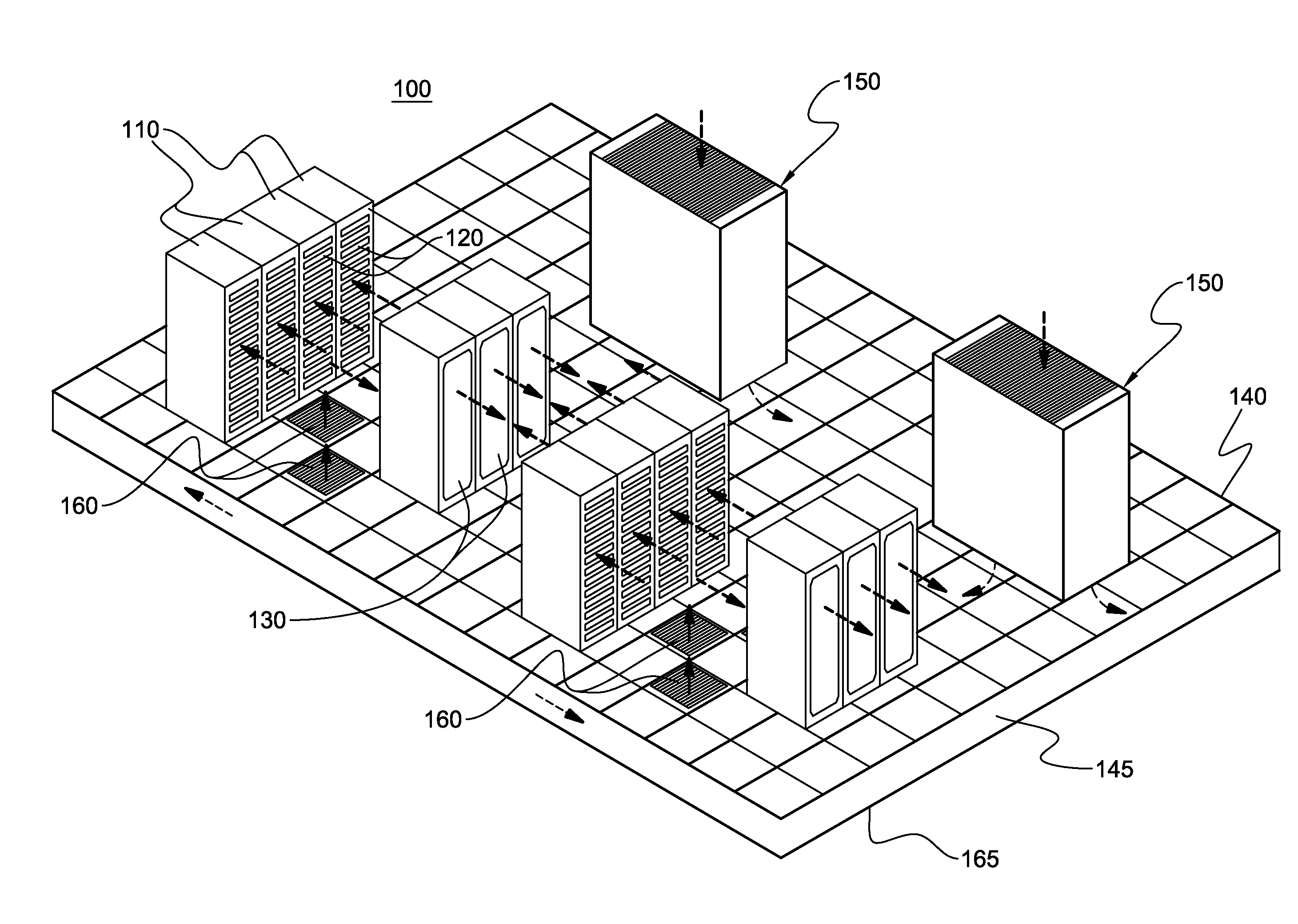
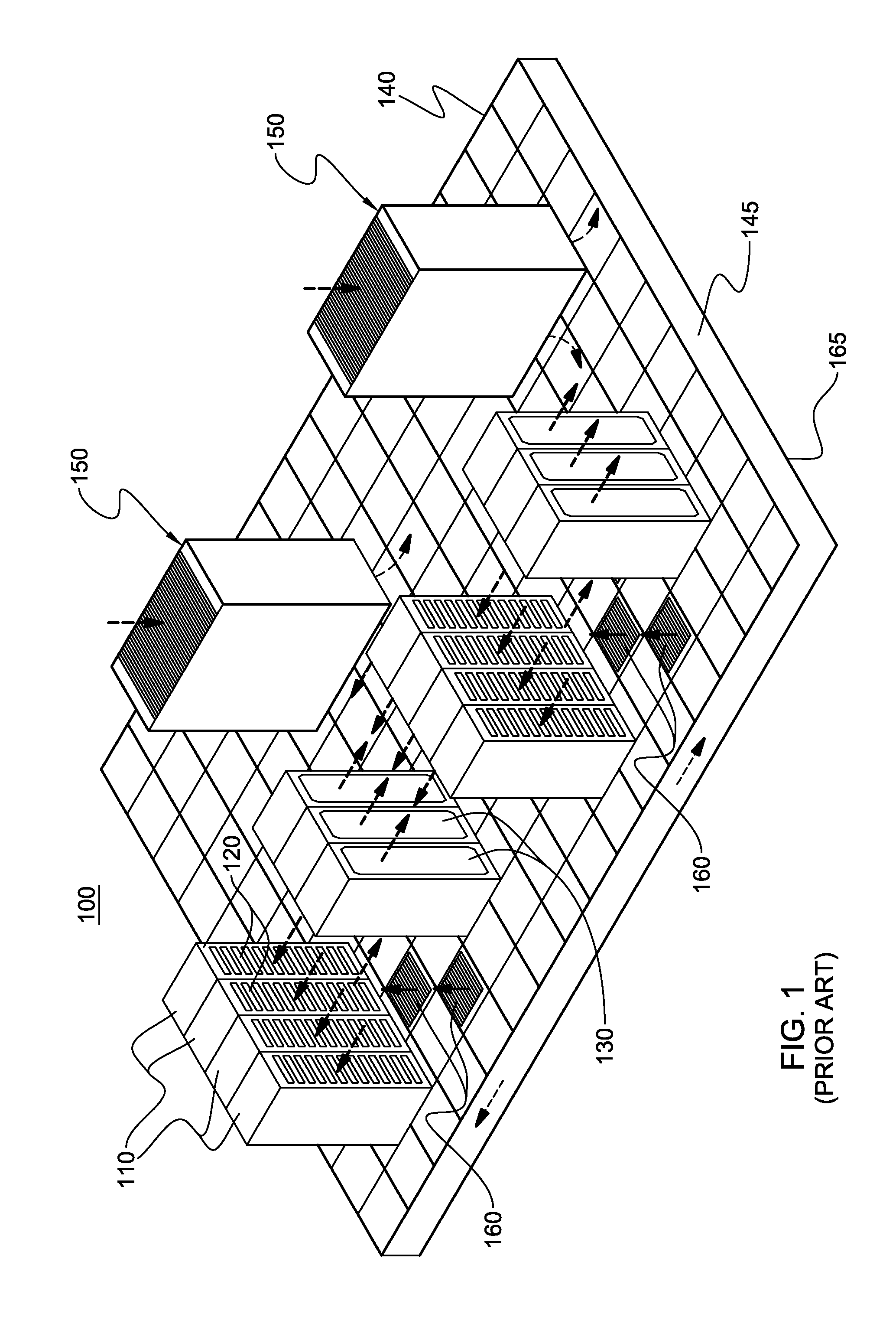
[0029]As used herein, the terms “electronics rack”, “rack-mounted electronic equipment”, and “rack unit” are used interchangeably, and unless otherwise specified include any housing, frame, rack, compartment, blade server system, etc., having one or more heat generating components of a computer system or electronics system, and may be, for example, a stand alone computer processor having high, mid or low end processing capability. In one embodiment, an electronics rack may comprise a portion of an electronic system, a single electronic system, or multiple electronic systems, for example, in one or more sub-housings, blades, books, drawers, nodes, compartments, etc., having one or more heat-generating electronic components disposed therein. An electronic system(s) within an electronics rack may be movable or fixed relative to the electronics rack, with the rack-mounted electronic drawers of a multi-drawer rack unit and blades of a blade center system being two examples of systems (or...


PUM

PropertyMeasurementUnit
inlet temperaturesaaaaaaaaaa
temperaturesaaaaaaaaaa

Abstract

An air-cooling apparatus is provided which includes a securing mechanism for holding two or more separate electronics racks in fixed relation adjacent to each other, and a multi-rack door sized and configured to span the air inlet or air outlet sides of the racks. The securing mechanism holds the electronics racks in fixed relation with their air inlet sides facing a first direction, and air outlet sides facing a second direction. The door includes a door frame with an airflow opening. The airflow opening facilitates the ingress or egress of airflow through the electronics racks, and the door further includes an air-to-liquid heat exchanger supported by the door frame, and disposed so that air flowing through the airflow opening passes across the heat exchanger. In operation, the heat exchanger extracts heat from the air passing through the separate electronics racks.

Description

CROSS-REFERENCE TO RELATED APPLICATIONS[0001]This application is a divisional application of U.S. application Ser. No. 13 / 115,404, filed May 25, 2011, and entitled “MULTI-RACK, DOOR-MOUNTED HEAT EXCHANGER”, which was published Nov. 29, 2012, as U.S. Patent Publication No. 2012-0300398 A1, and which is hereby incorporated herein by reference in its entirety.BACKGROUND[0002]The power dissipation of integrated circuit chips, and the modules containing the chips, continues to increase in order to achieve increases in processor performance. This trend poses a cooling challenge at both module and system levels. Increased airflow rates are needed to effectively cool high-powered modules, and to limit the temperature of the air that is exhausted into the computer center.[0003]In many large server applications, processors, along with their associated electronics (e.g., memory, disk drives, power supplies, etc.), are packaged in removable drawer configurations stacked within a rack or frame. ...

Claims


Application Information

Patent Timeline
Patent Type & Authority Applications(United States)
IPC IPC(8): H05K7/20B23P15/26
CPCB23P15/26H05K7/20718Y10T29/4935H05K7/2079H05K7/20818
Inventor ECKBERG, ERIC A.GRAYBILL, DAVID P.IYENGAR, MADHUSUDAN K.MAHANEY, JR., HOWARD V.SCHMIDT, ROGER R.SCHNEEBELI, KENNETH R.
Owner LENOVO GLOBAL TECH INT LTD
Why Eureka
Try Eureka