
Lighting device

a technology of lighting devices and light beams, which is applied in the direction of lighting and heating equipment, fixed installations, instruments, etc., can solve the problems of product design and design changes that are not easy, and the limit of making a thinner product, so as to enhance the degree of freedom in product design, reduce the number of light emitting units, and improve the effect of product design

Active Publication Date: 2014-02-13
LG INNOTEK CO LTD
View PDF3 Cites 25 Cited by
  • Summary
  • Abstract
  • Description
  • Claims
  • Application Information

AI Technical Summary

Benefits of technology

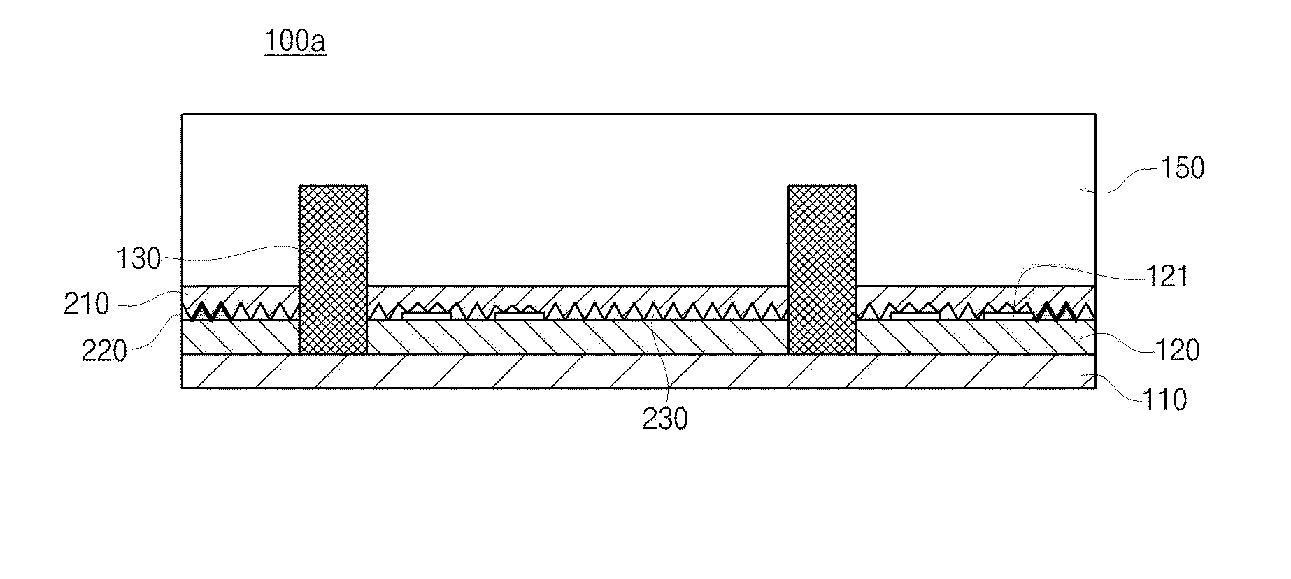
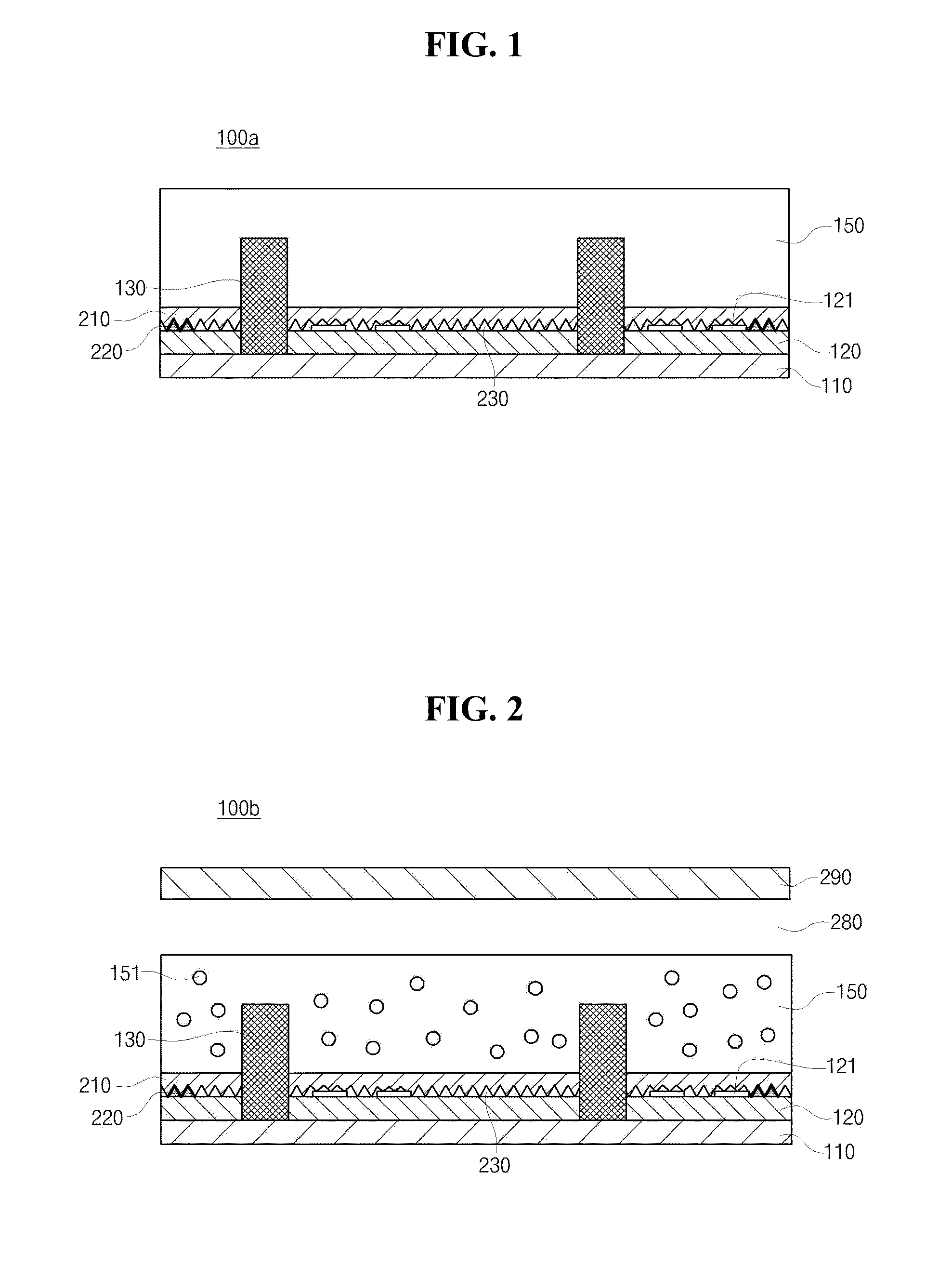
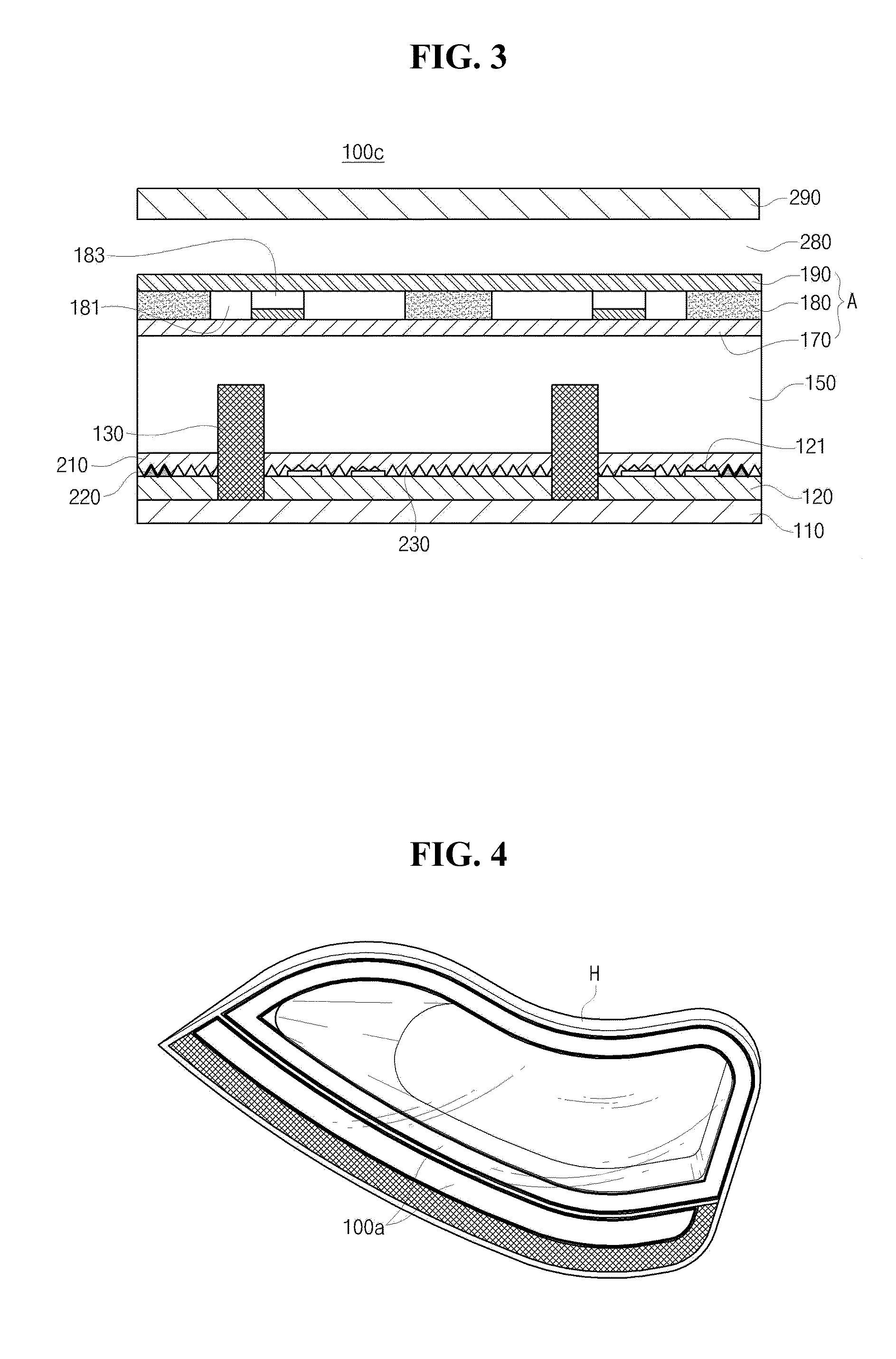
The present invention provides a lighting device with reduced number of light emitting units and a thinner overall thickness by removing a light guide plate and guiding light using a resin layer. The device is flexible and allows for product design flexibility. It also provides an optical member with a protrusion optical pattern that changes shape and a 3D feeling of light depending on viewing angle. The lighting device has an enhanced aesthetic feeling and can be applied to various fields. A reflection member and a reflection pattern are provided to efficiently reflect the light emitted from the light emitting units and maximize luminance and provide a uniform plane light source. The invention also provides a first optical substrate and a second optical substrate with an optical pattern each having an air gap to remove hot spots and enhance reliability of the elements adhered to the adhering layer.

Problems solved by technology

The light guide plate is used as a necessary element of the conventional lighting device 1; however it has a limit in making a thinner product owing to the thickness itself of the light guide plate.
Since the material of the light guide plate is not flexible, it cannot be applied to the external housing 50, etc. which has curved surfaces, so the product design and the design changes are not easy.

Method used


Image

  • Lighting device
  • Lighting device
  • Lighting device

Examples


Embodiment Construction

[0022]The embodiments of the present invention that an ordinary person skilled in the art can implement will be described with reference to the accompanying drawings. The embodiments in the specification and the constructions shown in the drawings are provided as a preferred embodiment of the present invention, and it should be understood that there may be various equivalents and modifications which could substitute at the time of filing. In addition, when it comes to the operation principle of the preferred embodiments of the present invention, when the known functions or functions are seemed to make unclear the subject matters of the present invention, they will be omitted from the descriptions of the invention. The terms below are defined in consideration of the functions of the present invention, and the meaning of each term should be interpreted by judging the whole parts of the present specification, and the elements having the similar functions and operations of the drawings ...


PUM


Abstract

Disclosed is a lighting device which comprises: an optical member comprising a protruding optical pattern forming a gap with an adjacent layer; at least one light emitting unit inserted into the optical member; and a resin layer formed on the optical member and the at least one light emitting unit, whereby it is possible to obtain an effect that the shapes of light change depending on the viewing angle when viewing the light source by producing various protruding optical patterns, an effect that the whole thickness can be reduced, and an effect that the degree of design freedom can be enhanced when designing products thanks to an enhanced flexibility.

Description

CROSS-REFERENCE TO RELATED APPLICATIONS[0001]This application claims the benefit under 35 U.S.C. §119 of Korean Patent Application Nos. 10-2012-0087769, filed Aug. 10, 2012 and 10-2013-0084347, filed Jul. 17, 2013, which are hereby incorporated by reference in their entirety.BACKGROUND[0002]1. Field of the Invention[0003]Embodiments of the present invention relate to a lighting device, and in particular to a lighting device structure which makes it possible to make the whole thickness thinner as such to obtain a high illuminating efficiency in such a way to remove a light guide plate and makes it possible to obtain an effect that the shape and a 3D effect of light change by forming a protrusion optical pattern.[0004]2. Description of Related Art[0005]The LED (Light Emitting Diode) device is directed to converting an electric signal into infrared ray or light using the natures of a compound semiconductor. Different from a fluorescent lamp, it does not use any harmful substances such ...

Claims


Application Information

Patent Timeline
Patent Type & Authority Applications(United States)
IPC IPC(8): F21V8/00
CPCG02B6/0088F21K9/68F21K9/69F21K9/60F21V5/04F21V7/00F21Y2115/10F21V13/04H01L25/0753H05K1/189H01L2933/0091H05K2201/10106H05K3/0064H05K2201/0108H05K2201/2054H01L2924/0002F21S43/14F21S43/26F21V5/008F21V5/02F21V5/004H01L2924/00F21V17/101F21V19/0015
Inventor YANG, HYUN DUCKKIM, JIN HEEKIM, CHUL HONGPARK, GWANG HOPARK, MOO RYOUNG
Owner LG INNOTEK CO LTD
Learn More