

Battery block and method for manufacturing same
a battery block and manufacturing method technology, applied in the field of battery blocks, can solve the problems of low heat dissipation property of resin containers, difficult to firmly fix one case to the other, and difficult to prevent short-circuits and other causes, and achieve the effect of sufficient durability
- Summary
- Abstract
- Description
- Claims
- Application Information
AI Technical Summary
Benefits of technology
Problems solved by technology
Method used
Image

Examples
embodiment 1
[0045]The battery block includes a battery case and cells. The battery case includes pipe-shaped members, and each of the cells is housed in a hollow part of each of the pipe-shaped members. The cells in the battery block may have charging property. In this case, the battery block functions as a high-capacity or high-output rechargeable battery.
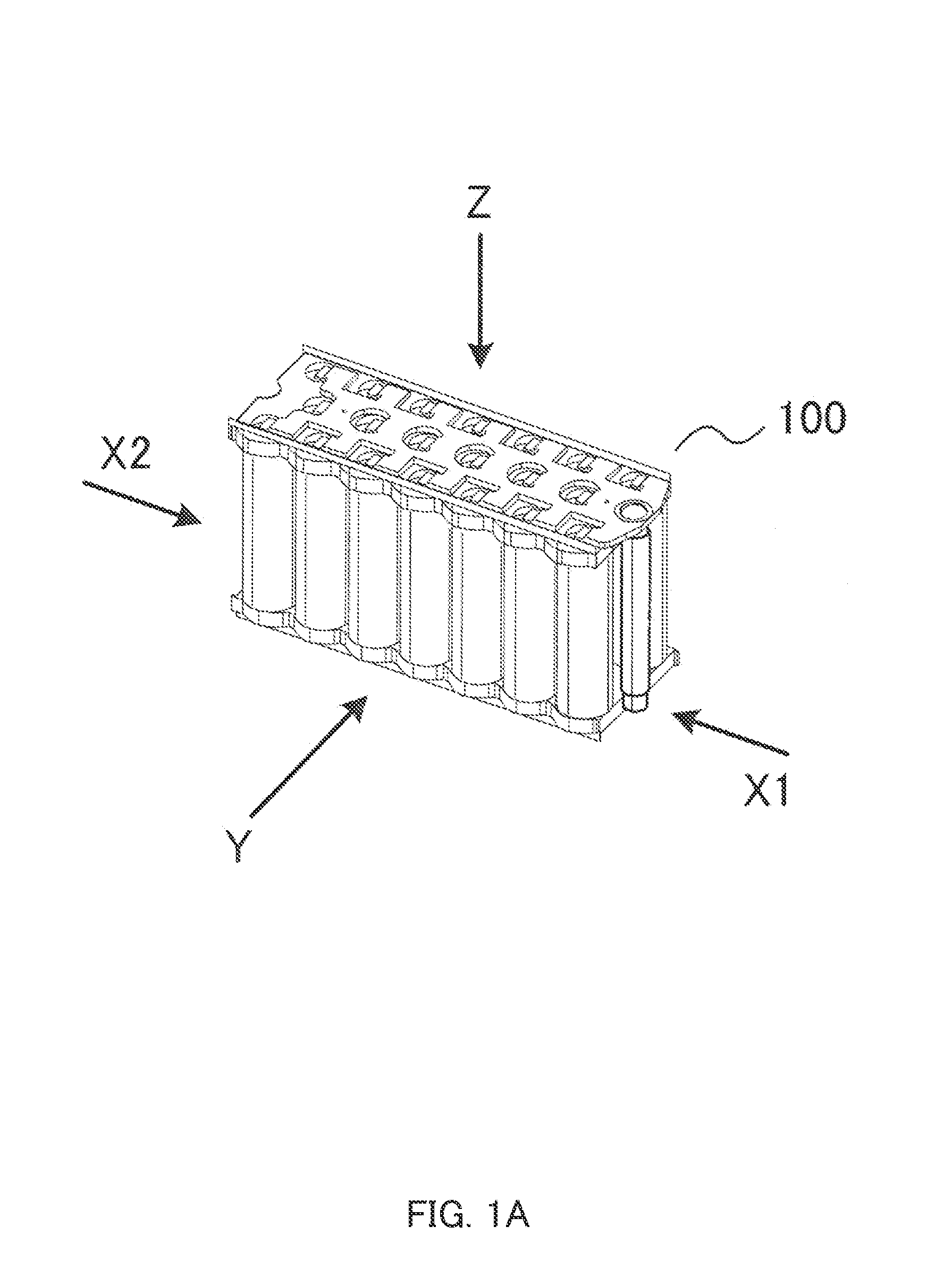
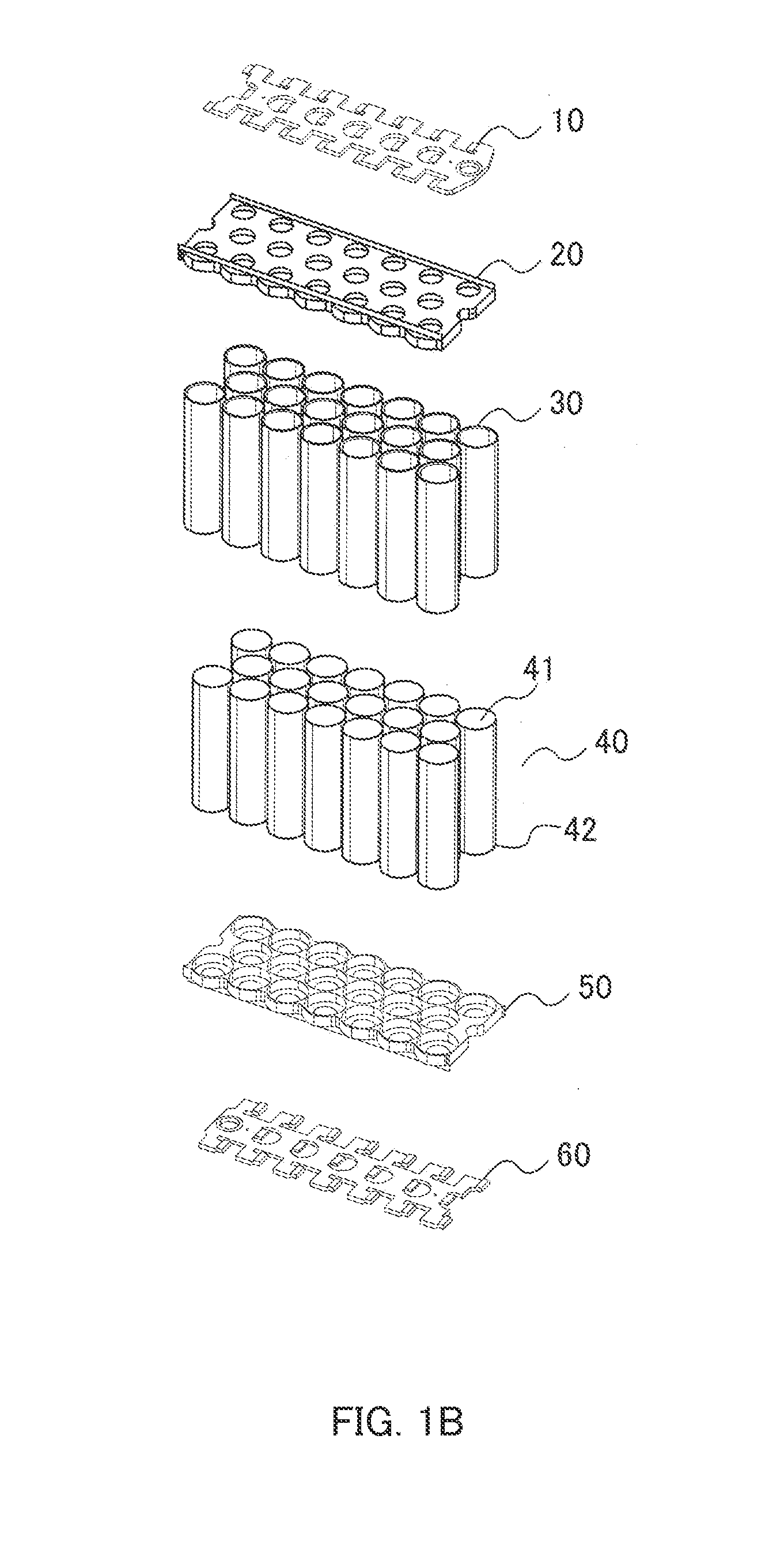
[0046]FIG. 1A is a schematic diagram illustrating battery block 100. FIG. 1B is an exploded perspective view illustrating battery block 100. As illustrated in FIG. 1B, battery block 100 includes electrode plate 10, holder 20, pipe-shaped members 30, cells 40, holder 50, and electrode plate 60.
[0047]Each of cells 40 is housed in pipe-shaped member 30. Cells 40 that are housed are held by holder 20 and holder 50. One electrode 41 of the cell is connected to electrode plate 10, and the other electrode 42 is connected to electrode plate 60.
[0048]As illustrated in FIG. 1B, each of cells 40 is housed in pipe-shaped member 30. An assembly of pipe-sh...
embodiment 2
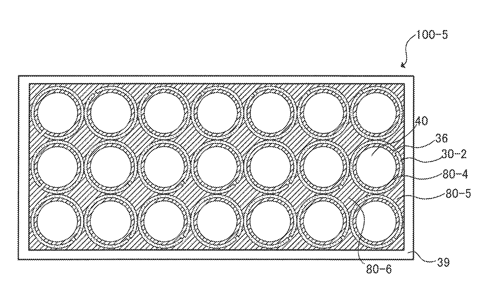
[0060]As illustrated in FIG. 7, battery block 100-4 according to Embodiment 2 includes (i) battery cases 30 and 30-2 including metal pipe-shaped members joined or bonded with one another, (ii) cell 40 housed in each of metal pipe-shaped members 30 and 30-2, and (iii) insulating layers 80-4 and 80-5 covering the inner wall surfaces or the outer wall surfaces of metal pipe-shaped members 30 and 30-2.
[0061]As illustrated in FIG. 7, metal pipe-shaped members 30-2 arranged at least at the outer periphery of battery block 100-4 each has cutout 36 at the end of the lateral side. Insulating layer 80-5 is formed continuous from a gap between the inner wall surface and call (80-4) to the outer wall surface via cutout 36. Insulating layer 80-4 formed between the inner wall surface and the cell and insulating layer 80-5 formed at the outer periphery of battery block 100-4 are integrally formed. Accordingly, the battery blocks are securely insulated from each other. The metal pipe-shaped members...
PUM
| Property | Measurement | Unit |
|---|---|---|
| temperature | aaaaa | aaaaa |
| temperature | aaaaa | aaaaa |
| heat-dissipating property | aaaaa | aaaaa |
Abstract
Description
Claims
Application Information