Switch mechanism for activating a switch while a display module pivots relative to a host module and portable electronic device therewith

a technology of switch mechanism and display module, which is applied in the direction of contact mechanism, portable computer, instruments, etc., can solve the problems of mechanical design difficulty, and achieve the effect of improving lack of activation accuracy and saving limited mechanical space of display modul

Active Publication Date: 2014-02-20
WISTRON CORP
View PDF3 Cites 6 Cited by
  • Summary
  • Abstract
  • Description
  • Claims
  • Application Information

AI Technical Summary

Benefits of technology

[0019]The switch mechanism and the portable electronic device therewith can switch a system of the portable electronic device into different states, such as the suspend state, the power-off state and the power-on state, by pivoting the display module relative to the host module to a predetermined angle. Because the activation component and the actuating portion of the switch mechanism are disposed inside the host module instead of the display module, so that it can save a limited mechanical space of the display module. In addition, because both the activation component and switch components are disposed in the host module, the predetermined activating angle of the switch components is not affected by material of the portable electronic device, so as to activate the switch components more accurately to improve lack of accuracy of activation as the casing of the notebook computer is made of non-plastic material, such as metal, to affect the magnetic field intensity of the Hall effect sensor.

Problems solved by technology

However, as the notebook becomes smaller and slimmer, a space for accommodating the Hall Effect switches inside the display module is getting smaller, resulting in difficulty of mechanical design.

Method used


Image

  • Switch mechanism for activating a switch while a display module pivots relative to a host module and portable electronic device therewith
  • Switch mechanism for activating a switch while a display module pivots relative to a host module and portable electronic device therewith
  • Switch mechanism for activating a switch while a display module pivots relative to a host module and portable electronic device therewith

Examples


Embodiment Construction

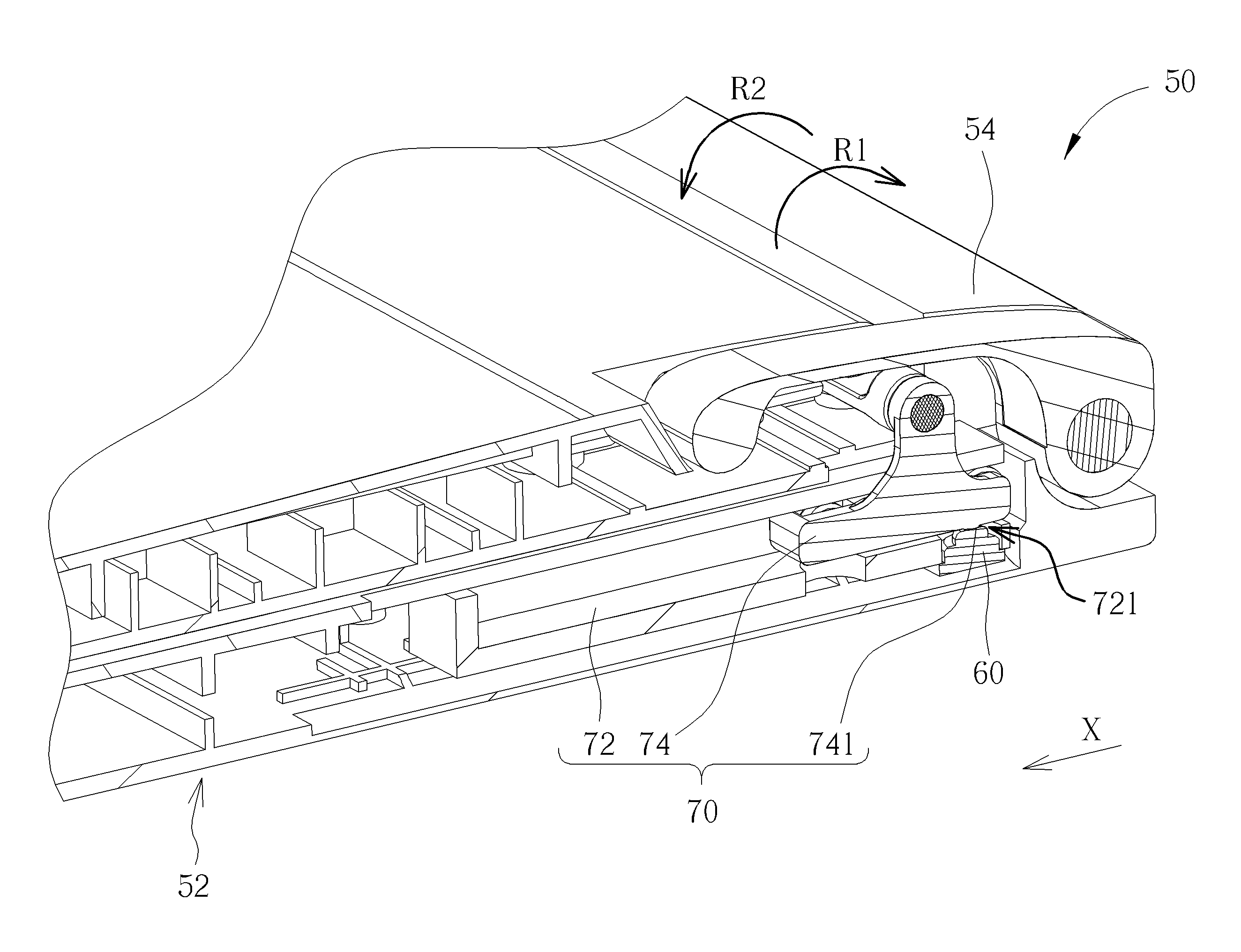
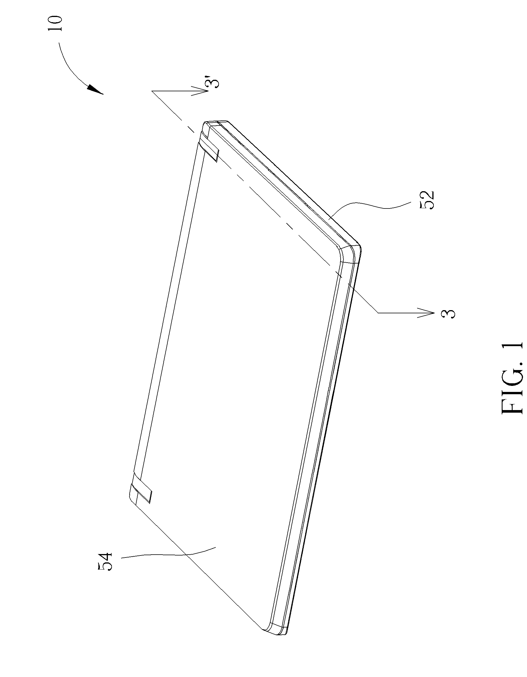
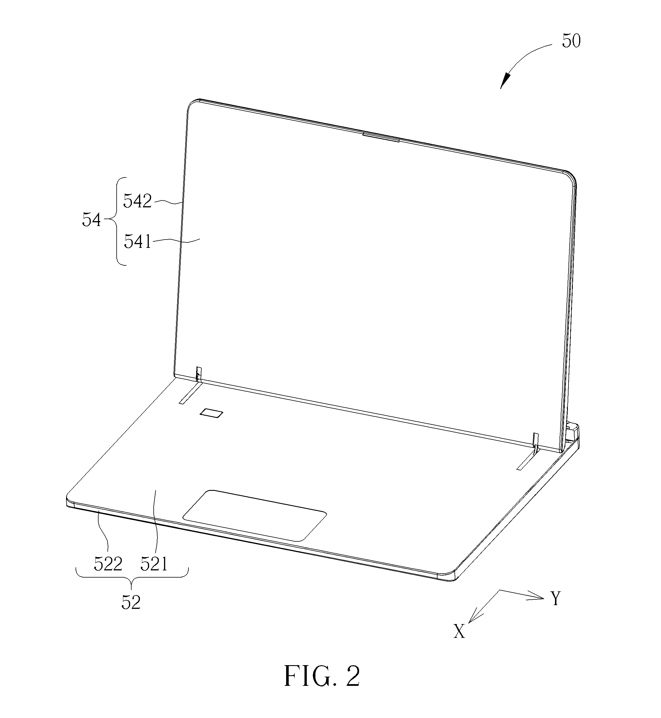
[0029]Please refer to FIG. 1 to FIG. 4. FIG. 1 and FIG. 2 are respectively diagrams of a portable electronic device 50 in different states according to an embodiment of the present invention. FIG. 3 is a sectional view of the portable electronic device 50 along section line 3-3′ illustrated in FIG. 1 according to the embodiment of the present invention. FIG. 4 is an inner structural diagram of the portable electronic device 50 illustrated in FIG. 2 according to the embodiment of the present invention. The portable electronic device 50 of the present invention can be a notebook computer, and so on. The portable electronic device 50 includes a host module 52. The host module 52 includes an upper casing 521 and a lower casing 522, and a combination of the upper casing 521 and the lower casing 522 can cover internal electronic components, such as a CPU, RAMs, an optical drive, a graphic card, connectors, and so on. The portable electronic device 50 further includes a display module 54. ...


PUM


Abstract

A switch mechanism includes a sliding track disposed inside a host module, and a sliding component. An end of the sliding component is pivotally connected to a display module and the other end of the sliding component is slidably installed inside the sliding track. The sliding component slides in a first direction relative to the sliding track while the display module pivots in a first rotary direction relative to the host module. The switch mechanism further includes an activation component for moving to a first position corresponding to a first switch component to activate a first switch component while the sliding component slides in the first direction.

Description

BACKGROUND OF THE INVENTION[0001]1. Field of the Invention[0002]The invention relates to a switch mechanism and a portable electronic device, and more specifically, to a switch mechanism for activating a switch while a display module pivots relative to a host module and a portable electronic device having the switch mechanism.[0003]2. Description of the Prior Art[0004]An operation system of a conventional notebook can switch to a suspend state or a power-off state while a display module and a host module are closed. An operation principle is to dispose a set of Hall effect switches on lateral sides of the display module, and the set of the Hall effect switches can be activated when an angle between the host module and the display module is less than a predetermined angle, so that the operation system can switch to the suspend state or the power-off state. However, as the notebook becomes smaller and slimmer, a space for accommodating the Hall Effect switches inside the display modul...

Claims


Application Information

Patent Timeline
Patent Type & Authority Applications(United States)
IPC IPC(8): H01H21/18
CPCH01H21/18G06F1/1616H01H3/162G06F1/1656G06F1/1677G06F1/1681G06F1/3218G06F1/3265Y02D10/00
Inventor WU, JING-TANGLEE, MING-HSIYU, LIANGWANG, PAO-CHUAN
Owner WISTRON CORP
Why Eureka
Try Eureka