
Wireless power system with capacitive proximity sensing

a capacitive proximity and power system technology, applied in the field of wireless power, can solve the problems of inconvenient or cumbersome cables and similar connectors, increasing the amount of power required by battery-powered electronic devices, and increasing the amount of power consumed

Active Publication Date: 2014-02-20
QUALCOMM INC
View PDF1 Cites 310 Cited by
  • Summary
  • Abstract
  • Description
  • Claims
  • Application Information

AI Technical Summary

Benefits of technology

The patent describes various aspects, advantages, and innovative features of the invention. However, not all advantages may be present in every embodiment of the invention. The invention may be implemented in a way that optimizes certain advantages without necessarily achieving all other advantages in the patent.

Problems solved by technology

While battery technology has improved, battery-powered electronic devices increasingly require and consume greater amounts of power, thereby often requiring recharging.
Cables and similar connectors may sometimes be inconvenient or cumbersome and have other drawbacks.

Method used


Image

  • Wireless power system with capacitive proximity sensing
  • Wireless power system with capacitive proximity sensing
  • Wireless power system with capacitive proximity sensing

Examples


Embodiment Construction

[0032]The detailed description set forth below in connection with the appended drawings is intended as a description of exemplary embodiments of the invention and is not intended to represent the only embodiments in which the invention may be practiced. The term “exemplary” used throughout this description means “serving as an example, instance, or illustration,” and should not necessarily be construed as preferred or advantageous over other exemplary embodiments. The detailed description includes specific details for the purpose of providing a thorough understanding of the exemplary embodiments of the invention. In some instances, some devices are shown in block diagram form.

[0033]Wirelessly transferring power may refer to transferring any form of energy associated with electric fields, magnetic fields, electromagnetic fields, or otherwise from a transmitter to a receiver without the use of physical electrical conductors (e.g., power may be transferred through free space). The powe...


PUM


Abstract

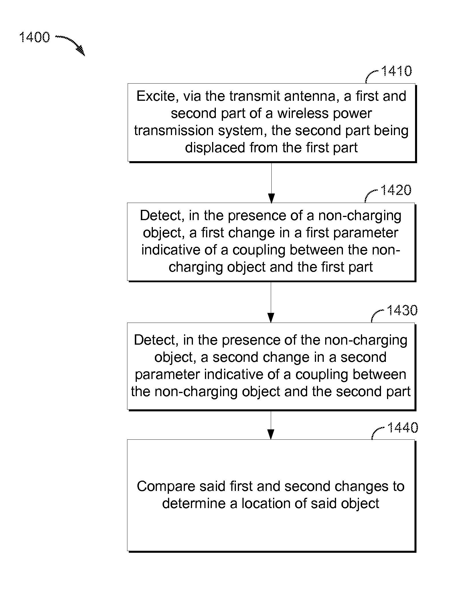
This disclosure provides systems, methods and apparatus for tuning a transmit coil for operation in a plurality of frequency bands. In one aspect, a method of wireless power transmission is provided. The method includes exciting a first part of a wireless power transmission system, via a wireless power transmitter. The method further includes detecting, in the presence of a non-charging object, a first change in a first parameter. The first parameter is indicative of a coupling between the non-charging object and the first part. The method further includes varying a characteristic of the wireless power transmission based on said first change.

Description

CROSS-REFERENCE TO RELATED APPLICATIONS[0001]This application claims priority under 35 U.S.C. §119(e) to U.S. Provisional App. No. 61 / 684626, filed Aug. 17, 2012, which is incorporated by reference herein in its entirety.FIELD[0002]The present invention relates generally to wireless power. More specifically, the disclosure is directed to wireless power systems capable of capacitive proximity sensing.BACKGROUND[0003]An increasing number and variety of electronic devices are powered via rechargeable batteries. Such devices include mobile phones, portable music players, laptop computers, tablet computers, computer peripheral devices, communication devices (e.g., Bluetooth devices), digital cameras, hearing aids, and the like. While battery technology has improved, battery-powered electronic devices increasingly require and consume greater amounts of power, thereby often requiring recharging. Rechargeable devices are often charged via wired connections through cables or other similar co...

Claims


Application Information

Patent Timeline
Patent Type & Authority Applications(United States)
IPC IPC(8): H02J17/00G01S13/06
CPCH02J50/90H02J50/05H02J50/12H02J50/60H02J50/40H02J7/00034H04B5/22H04B5/79H02J7/00
Inventor VON NOVAK, WILLIAM H.MONAT, PAVELKALLAL, EDWARD
Owner QUALCOMM INC
Learn More