Lens focusing device

Active Publication Date: 2014-02-20
TDK TAIWAN
View PDF6 Cites 14 Cited by
  • Summary
  • Abstract
  • Description
  • Claims
  • Application Information

AI Technical Summary

Benefits of technology

The present invention is a lens focusing device that allows for easy and accurate connection of terminals to a conductive spring member for good electrical connection. The device includes a terminal recess with a receiving groove, a communicating groove, and a notch, which allows for easy assembly of connecting terminals to the base. The connecting terminals have extended first and second terminal portions towards the light-in and out sides of the device, ensuring good electrical connection with the spring member and easy connection to external circuit boards. The spring member has multiple outer ring portions with through holes, and the first terminal portions have a projected portion that connects with the spring member. This results in a continuous and smooth supply of electric current to the spring member and effective protection of the connecting terminals. Overall, the lens focusing device of the present invention is advantageous in production because it includes terminals for supplying electric power to the winding, and the power supply terminals can be easily and accurately assembled to the base and the spring member.

Problems solved by technology

While the power supply terminals integrally formed with the spring plate can ensure good electrical conductivity thereof, they must be extended through a base of the lens focusing device during assembling to cause troubles in manufacturing process of the lens focusing device.
Thus, it is necessary to make certain the embedded power supply terminals and the spring plate are in good electrical connection to one another because poor or bad electrical connection of the power supply terminals to the spring plate would result in defects in the completed lens focusing device.

Method used


Image

  • Lens focusing device
  • Lens focusing device
  • Lens focusing device

Examples


Embodiment Construction

[0023]The present invention will now be described with some preferred embodiments thereof and with reference to the accompanying drawings.

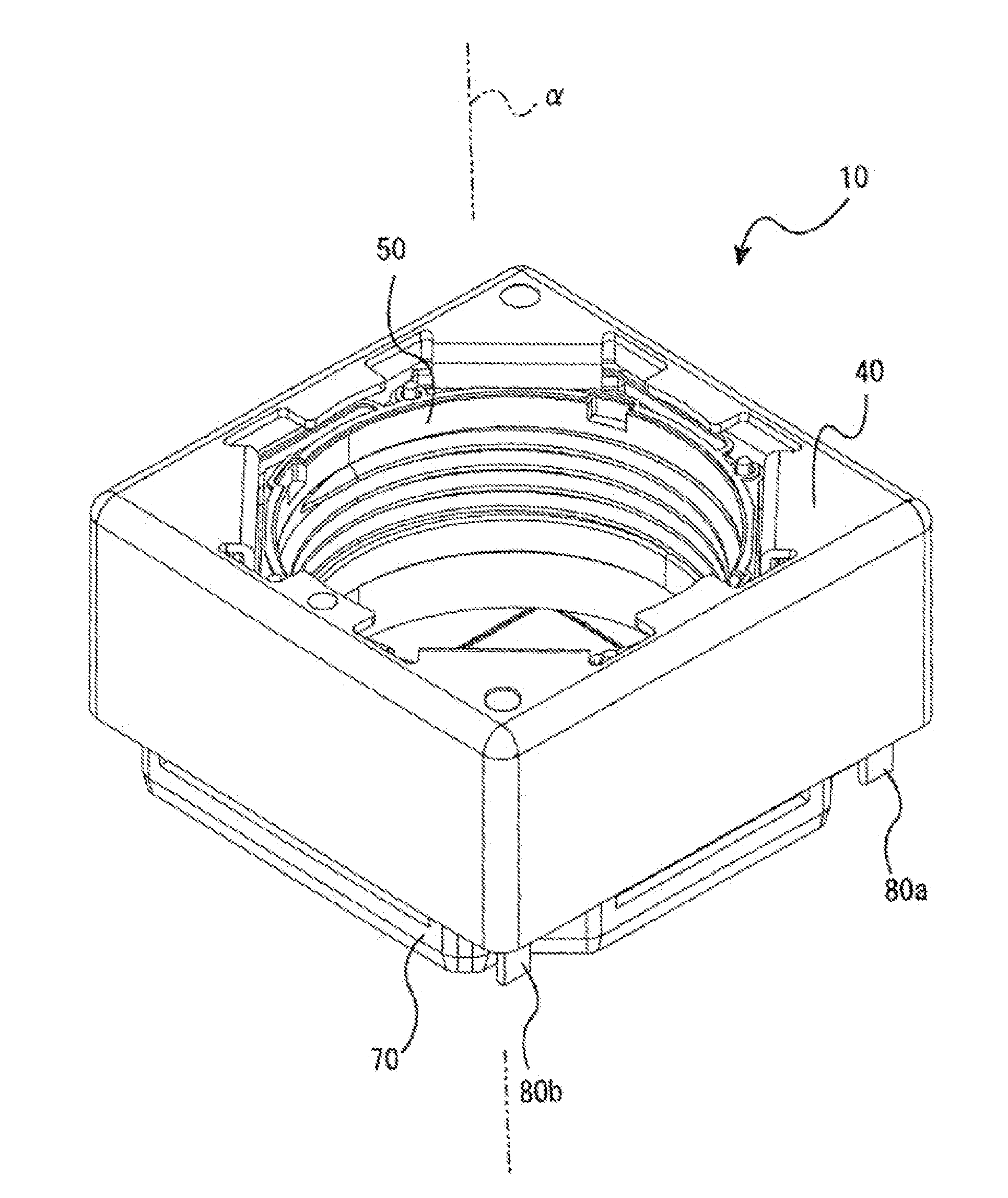
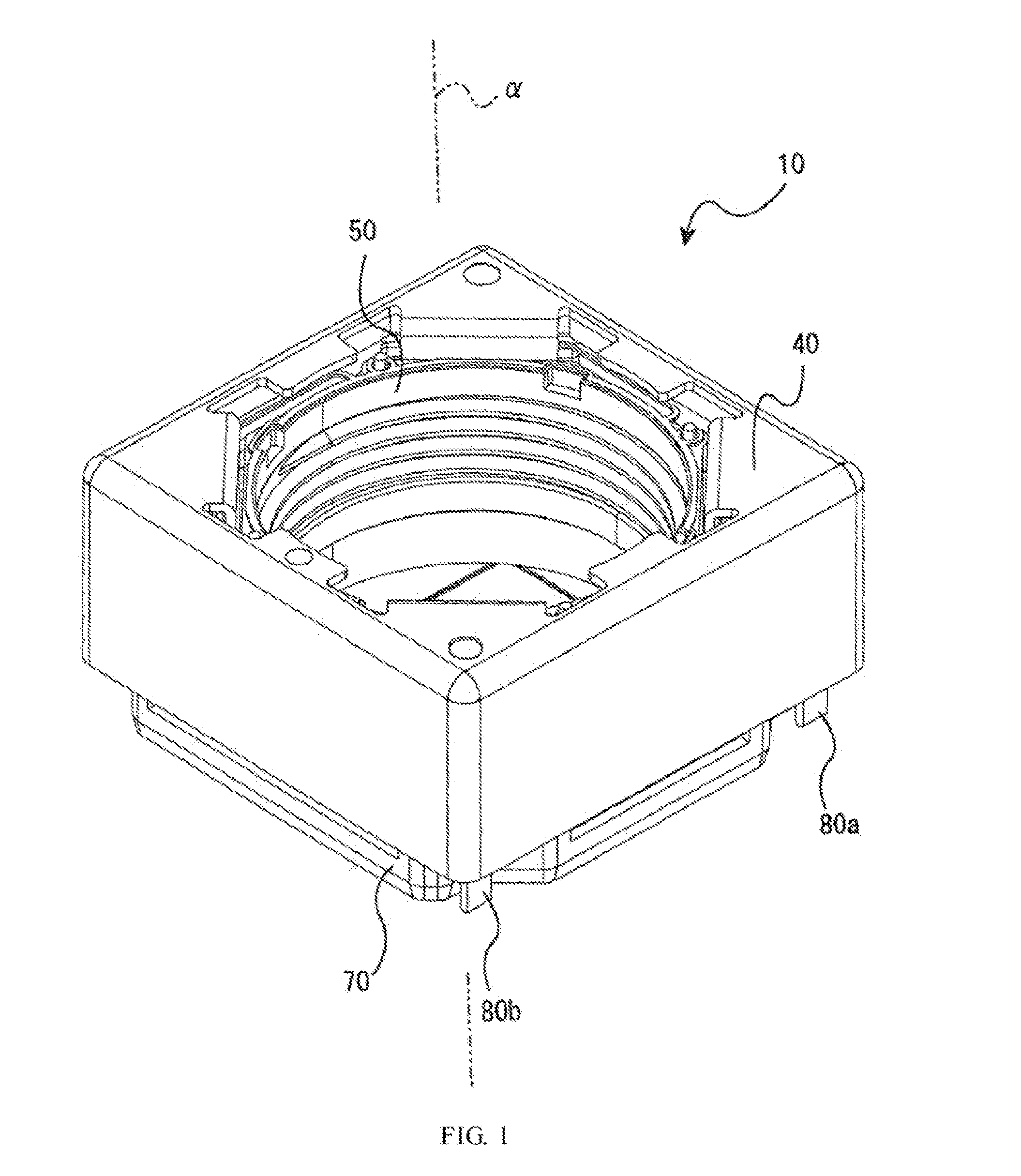
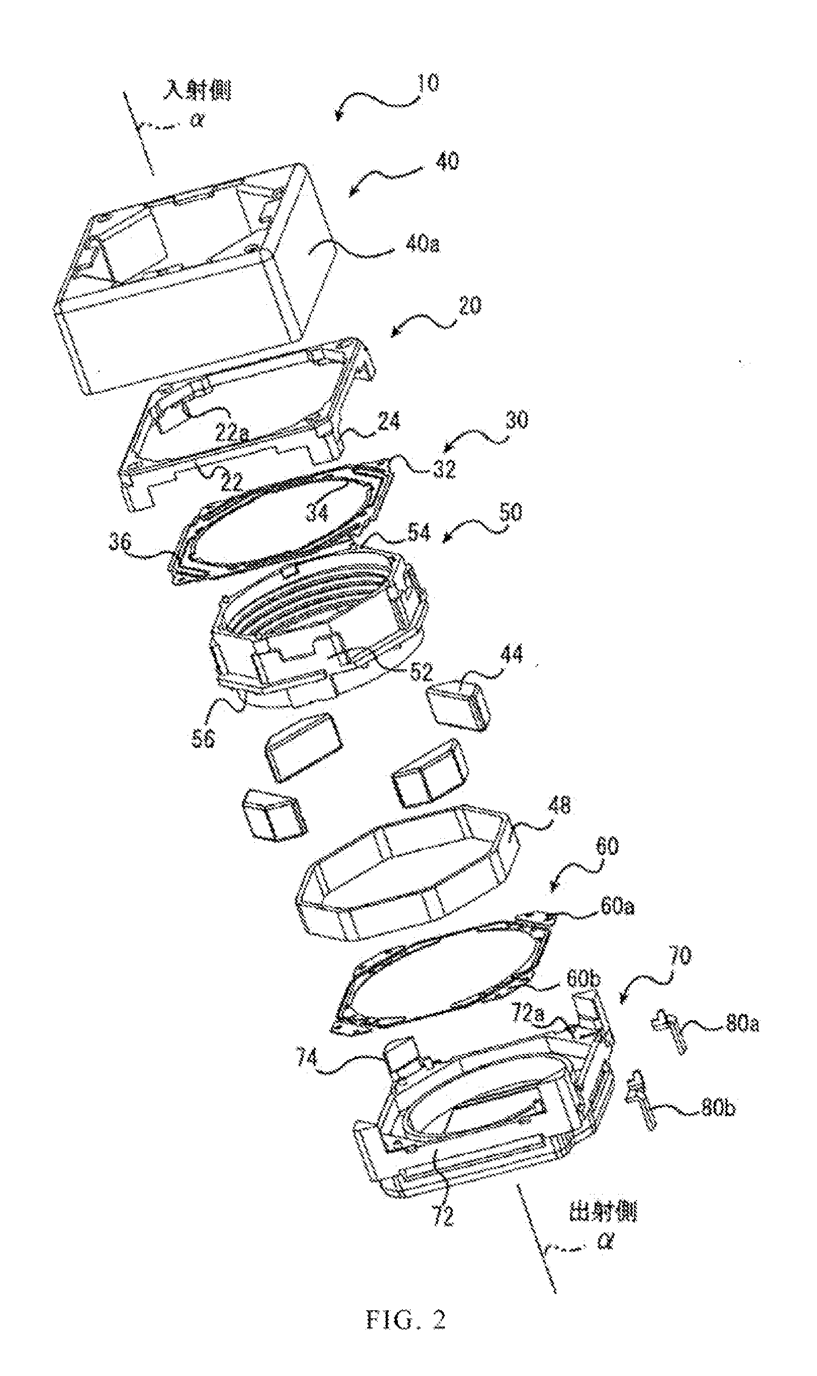
[0024]Please refer to FIGS. 1 and 2 that are assembled and exploded perspective views, respectively, of a lens focusing device 10 according to an embodiment of the present invention. As shown, the lens focusing device 10 has a substantially rectangular appearance, and mainly includes a lens holder 50, a yoke 40, and a base 70. The lens holder 50 is located at a central portion of the lens focusing device 10 for holding a lens therein (not shown). The yoke 40 is located at an outer side of the lens holder 50 to enclose the lens holder 50 and the base 70 therein.

[0025]The base 70 supports the lens holder 50 thereon, such that the lens holder 50 is movable relative to the base 70 for focusing purpose. The lens focusing device 10 internally includes a voice coil motor, which drives the lens holder 50 to move relative to the base 70 along a light axis ...


PUM


Abstract

A lens focusing device includes a lens holder for holding a lens therein, a base, and an electrically conductive spring member elastically connected to between the lens holder and the base. The base is provided on a side wall with two terminal recesses, in which two connecting terminals are disposed. The connecting terminals respectively include a first terminal portion forward extended along a light axis to electrically connect to the spring member, a second terminal portion rearward extended along the light axis, and a connecting portion located between the first and the second terminal portion. The spring member is further electrically connected to two ends of a winding wound around the lens holder, so that external electric current can be supplied to the winding via the connecting terminals and the spring member for driving the lens holder to move relative to the base along the light axis.

Description

FIELD OF THE INVENTION[0001]The present invention relates to a lens focusing device, and more particularly to a lens focusing device that can be used with a cell phone or a camera for shooting pictures.BACKGROUND OF THE INVENTION[0002]Generally, a lens focusing device can be used with a variety of handheld devices, such as cell phones, cameras, tablet computers, notebook computers and the like, as well as with various types of webcams, to serve as a lens auto-focusing means during picture shooting.[0003]The lens focusing device includes at least two power supply terminals for connecting to an external circuit board, such as the circuit board of the cell phone, so that electric power or electric signals can be provided via the power supply terminals to a voice coil motor in the lens focusing device for driving a lens holder to move forward and rearward for focusing purpose.[0004]In a conventional lens focusing device, the power supply terminals thereof are either integrally formed wi...

Claims


Application Information

Patent Timeline
IPC IPC(8): G02B7/04
CPCG02B7/08H02K41/0356
Inventor HSU, SHANG-YULIN, KUN-SHIHWU, FU-YUAN
Owner TDK TAIWAN
Why Eureka
Try Eureka