Method of manufacturing stator coil for electric rotating machine

a technology of electric rotating machines and stator coils, which is applied in the manufacture of dynamo-electric machines, electrical apparatus, dynamo-electric machines, etc., can solve the problems of affecting the service life of the electric wire, the in-slot portion of the in-slot portion of the electric wire may be damaged, and the stator coil and the stator core are difficult to easily and accurately assembled, so as to prevent radial misalignment, shorten the length of each electric wir

Active Publication Date: 2013-01-17
DENSO CORP
View PDF1 Cites 7 Cited by
  • Summary
  • Abstract
  • Description
  • Claims
  • Application Information

AI Technical Summary

Benefits of technology

[0011]With the above method, since each of the electric wires is rolled through plastic deformation of the turn portions in the rolling step, no spring back of the electric wires will occur after the rolling step. Consequently, it is possible to reliably prevent radial misalignment between the corresponding in-slot portions of the electric wires from occurring in the resultant stator coil, thereby reliably keeping the hollow cylindrical shape of the stator coil.
[0012]Moreover, compared to the method disclosed in Japanese Patent Application Publication No. 2001-145286, it is possible to shorten the length of each of the electric wires. Consequently, the electric wires can be shaped using a smaller-scale shaping machine and be more easily handled during the manufacture of the stator coil. As a result, it is possible to achieve a higher productivity and a lower cost of the stator coil.
[0013]Further, since each of the relative axial movements in the assembling step is made with both the first and second components radially elastically deformed, it is possible to prevent interference between the first and second components from occurring during the relative axial movement. Consequently, without interference therebetween, the first and second components can be smoothly moved relative to each other, thereby facilitating the assembly of the first and second components. Moreover, the insulating coats of the electric wires of the first and second components can be reliably prevented from being damaged due to interference between the first and second components.
[0014]Furthermore, since each of the relative axial movements in the assembling step is made with each of the first and second components circumferentially positioned by at least one positioning member, it is possible to more reliably ensure that the corresponding in-slot portions of the electric wires of the first and second components be accurately radially aligned with each other. As a result, with the accurately radially-aligned corresponding in-slot portions of the electric wires, it is possible to more easily and accurately assemble the stator core to the resultant stator coil.

Problems solved by technology

However, due to springback of the electric wires which are only elastically deformed during the rolling step, it may be easy for radial misalignment between the corresponding in-slot portions of the electric wires to occur, rendering it difficult to keep the hollow cylindrical shape of the stator coil.
Consequently, it may be difficult to easily and accurately assemble the stator coil and the stator core.
However, in this case, insulating coats formed at the surfaces of the in-slot portions of the electric wires may be damaged due to friction which may occur between adjacent pairs of the in-slot portions of the electric wires during the rolling step.
Consequently, it may be difficult to ensure electrical insulation between the in-slot portions of the electric wires.
In addition, with the long length of the electric wires, it may be difficult to handle the electric wires during the manufacture of the stator.
As a result, it may be difficult to secure a high productivity and a low cost of the stator.

Method used


Image

  • Method of manufacturing stator coil for electric rotating machine
  • Method of manufacturing stator coil for electric rotating machine
  • Method of manufacturing stator coil for electric rotating machine

Examples


first embodiment

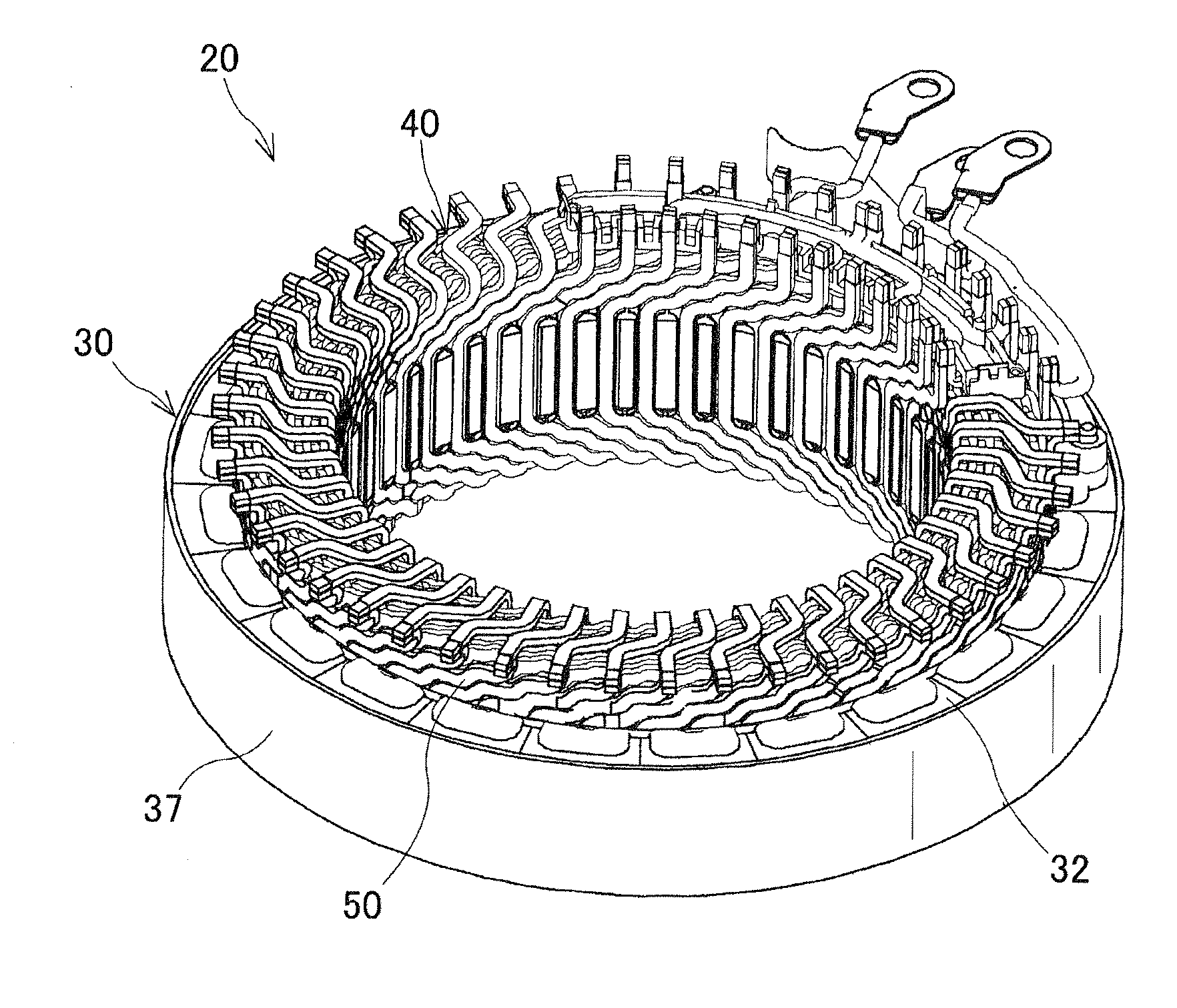
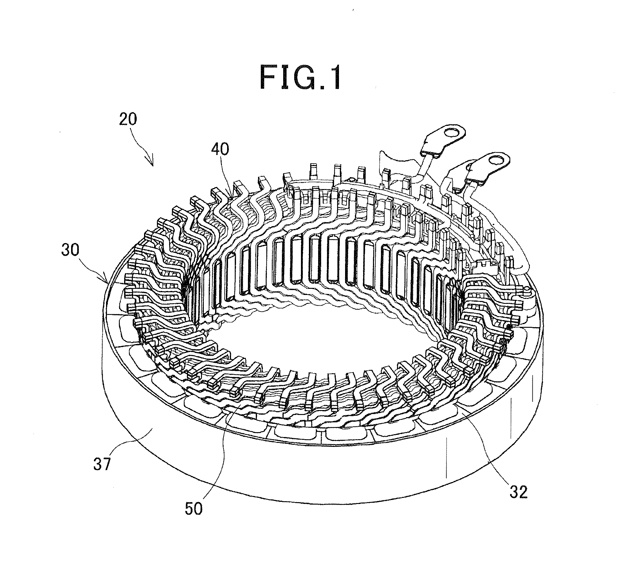
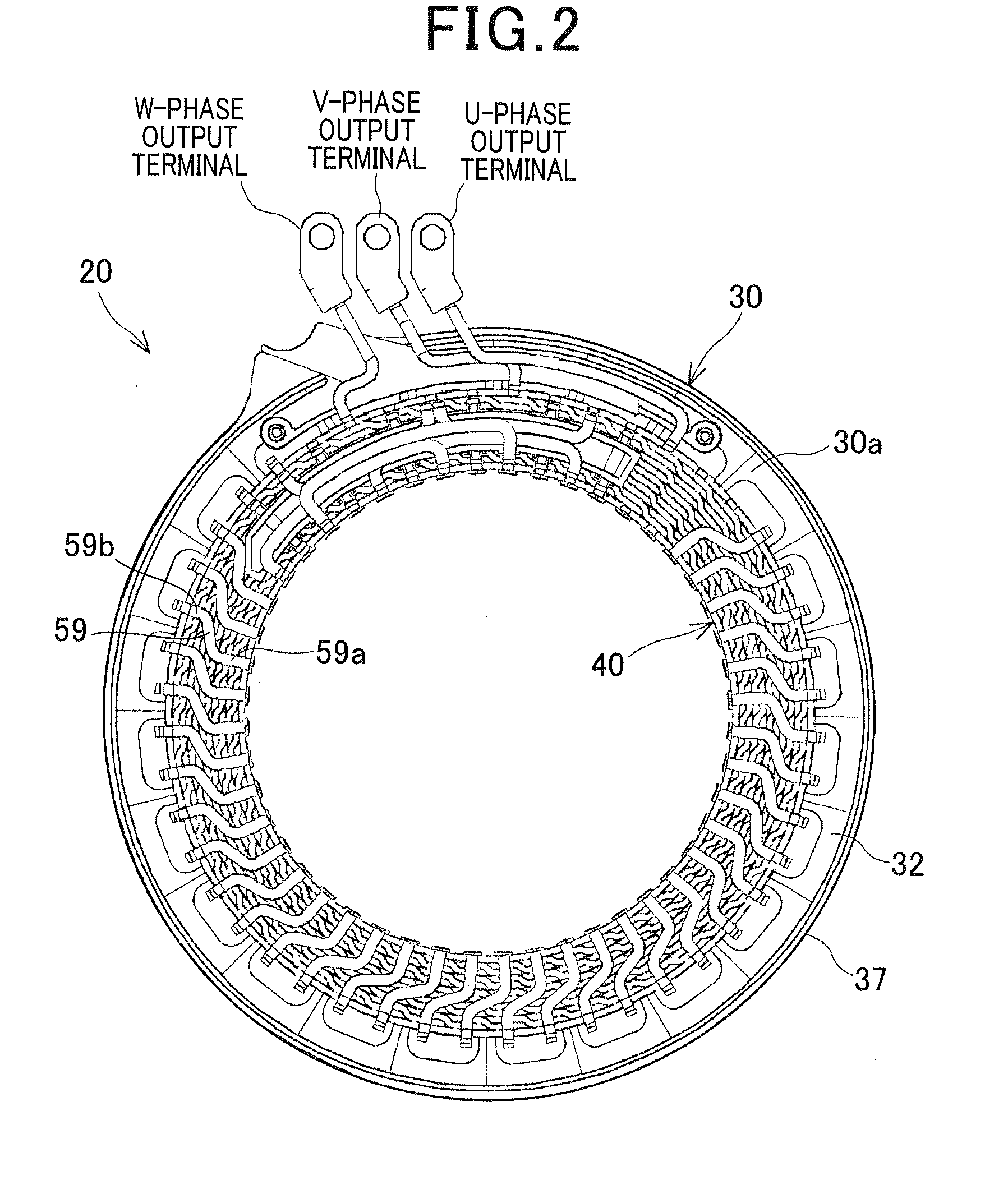
[0066]FIGS. 1-3 together show the overall configuration of a stator 20 which includes a three-phase stator coil 40 manufactured by a method according a first embodiment.

[0067]The stator 20 is designed to be used in, for example, an electric rotating machine (not shown) that can function both as an electric motor and as an electric generator in a motor vehicle.

[0068]In addition to the stator 20, the electric rotating machine further includes a rotor (not shown) that is rotatably disposed radially inside of the stator 20. The rotor includes a plurality of permanent magnets that form a plurality of magnetic poles on the radially outer periphery of the rotor to face the radially inner periphery of the stator 20. The magnetic poles are spaced in the circumferential direction of the rotor at predetermined intervals so that the polarities of the magnetic poles alternate between north and south in the circumferential direction. In addition, the number of the magnetic poles formed in the rot...

second embodiment

[0217]This embodiment illustrates a method of manufacturing the stator coil 40 which is similar to the method according to the first embodiment; accordingly, only the differences therebetween will be described hereinafter.

[0218]In the first embodiment, the first to the sixth positioning members 90a-90f are used in the assembly step 103. The first and second positioning members 90a and 90b are axially located on the side of the first volute jig 85A, while the third to the sixth positioning members 90c-90f are axially located on the side of the second volute jig 85B. Each of the first and second volute jigs 85A and 85B has the windows 86 formed therein. All the first to the sixth positioning members 90a-90f are configured to be radially advanced and retreated without moving in the axial direction.

[0219]In comparison, in the present embodiment, referring to FIGS. 29A-29D, only the first to the third positioning members 90a-90c are used in the assembly step 103. The first positioning me...

third embodiment

[0235]This embodiment illustrates a method of manufacturing the stator coil 40 which is similar to the method according to the first embodiment; accordingly, only the differences therebetween will be described hereinafter.

[0236]In the first embodiment, the first and second volute jigs 85A and 85B are used to respectively radially elastically deform the first and second components 61 and 62 during each of the assembly processes in the assembly step 103 (see FIGS. 22A-22B).

[0237]In comparison, in the present embodiment, first and second sets of rotatable plates are used to respectively radially elastically deform the first and second components 61 and 62 during each of the assembly processes in the assembly step 103.

[0238]Specifically, as shown in FIGS. 30A-30B, each of the first and second rotatable plate sets consists of a plurality (e.g., 11 in the present embodiment) of rotatable plates 87 that are spirally arranged. Each of the rotatable plates 87 has a substantially elliptical c...


PUM

PropertyMeasurementUnit
thicknessesaaaaaaaaaa
internal anglesaaaaaaaaaa
rotationaaaaaaaaaa

Abstract

A method of manufacturing a stator coil includes the steps of: (1) forming substantially planar electric wires each including in-slot portions to be received in slots of a stator core and turn portions to be located outside of the slots to connect the in-slot portions; (2) rolling each of the planar electric wires into a spiral shape by plastically deforming the turn portions; and (3) assembling the rolled electric wires through relative axial movements therebetween, each of the relative axial movements being made by axially moving first and second components relative to each other with both the first and second components radially elastically deformed and with each of the first and second components circumferentially positioned by at least one positioning member, each of the first and second components being one of the rolled electric wires or an electric wire sub-assembly comprised of a plurality of the rolled electric wires.

Description

CROSS-REFERENCE TO RELATED APPLICATION[0001]This application is based on and claims priority from Japanese Patent Application No. 2011-154717, filed on Jul. 13, 2011, the content of which is hereby incorporated by reference in its entirety into this application.BACKGROUND[0002]1. Technical Field[0003]The present invention relates to methods of manufacturing stator coils for electric rotating machines that are used in, for example, motor vehicles as electric motors and electric generators.[0004]2. Description of the Related Art[0005]There are known stators for electric rotating machines which include a hollow cylindrical stator core and a stator coil. The stator core has a plurality of slots that are formed in the radially inner surface of the stator core and spaced at equal intervals in the circumferential direction of the stator core. The stator coil is comprised of a plurality of electric wires mounted on the stator core. Each of the electric wires includes a plurality of in-slot ...

Claims


Application Information

Patent Timeline
Patent Type & Authority Applications(United States)
IPC IPC(8): H02K15/04
CPCH02K3/28Y10T29/49009H02K15/0478
Inventor KAYUKAWA, KIMIHARUDOBASHI, MASAOMISHIMAOKA, HIDEJIKAMAKURA, YOUICHI
Owner DENSO CORP
Why Eureka
Try Eureka