Rotation detection sensor mounting structure and hub unit

A technology of rotation detection and installation structure, applied in the field of hub unit, can solve problems such as the inability to guarantee the stable output and detection of the sensor, the need for stability and safety, and the inability to guarantee the detection of wheel rotation.

Inactive Publication Date: 2016-03-16
JTEKT CORP
View PDF8 Cites 0 Cited by
  • Summary
  • Abstract
  • Description
  • Claims
  • Application Information

AI Technical Summary

Problems solved by technology

[0009] Incidentally, since the sensor is installed in a state where it is exposed to the outside, there is a concern that the sensor may be dislocated from the supporting ring member due to foreign matter colliding with the sensor when the vehicle is driven or under some climatic conditions, so that the rotation of the wheel cannot be ensured. detection, and therefore, require more stability and safety than sensor assembly and operational characteristics
[0010] In addition, for the structure in which the elastically deformed clip part is pressed against the sensor to fix it, once creep occurs in the clip part due to thermal changes in the clip part or the clip part is pressed by the spring part for a long time, the force to fix the sensor decreases , and even in the case where a claw portion (rotation restraining means) is formed adjacent to the lower end of the front surface of the sensor, it is no longer possible to fix the sensor in a stable manner, and in a worse case, causing a failure to ensure stable sensor output and detection concerns

Method used


Image

  • Rotation detection sensor mounting structure and hub unit
  • Rotation detection sensor mounting structure and hub unit
  • Rotation detection sensor mounting structure and hub unit

Examples


no. 1 example

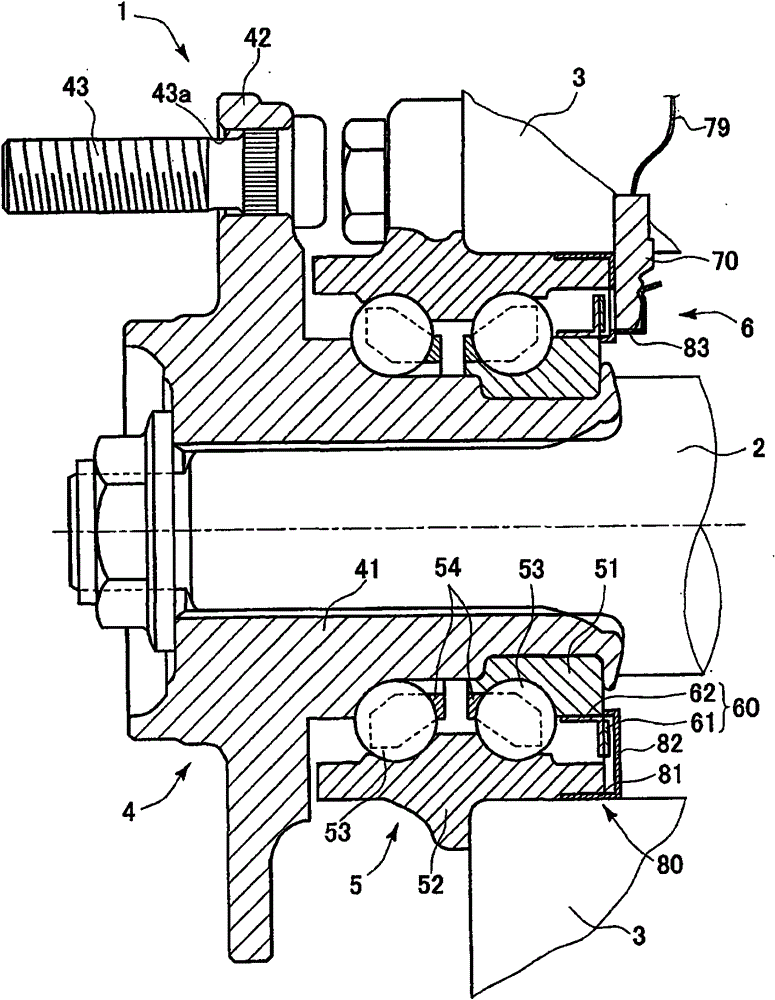
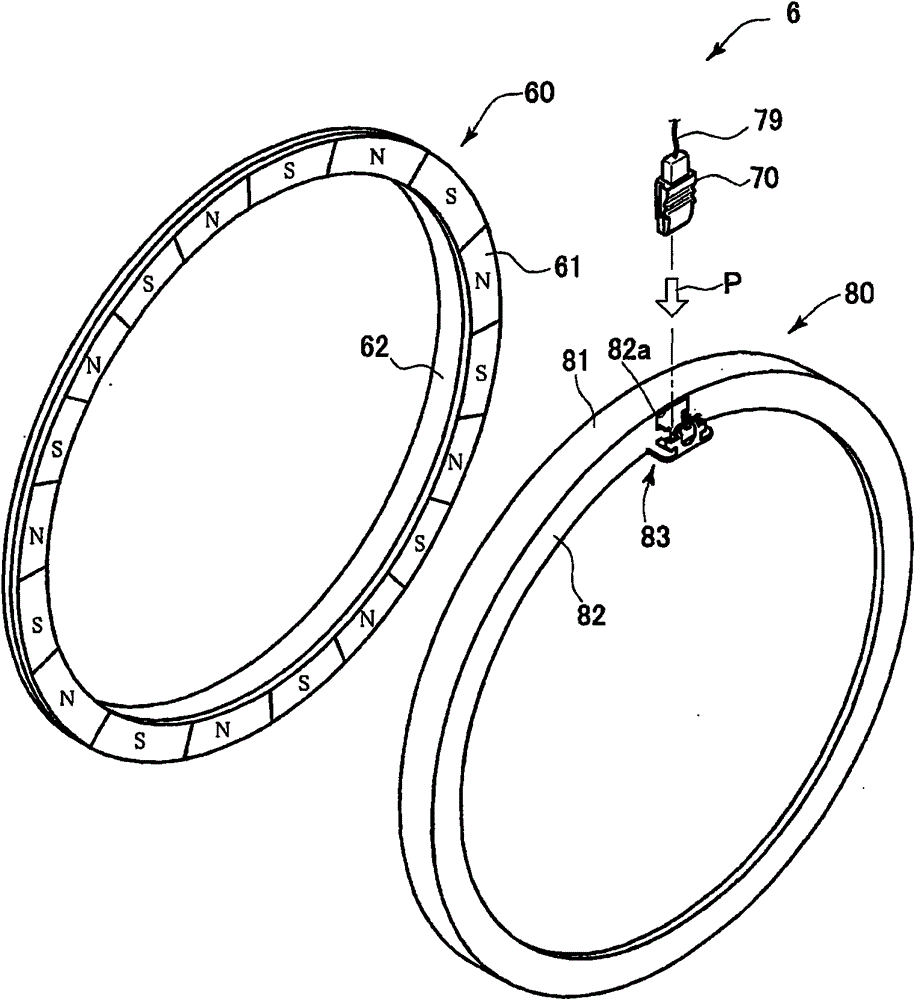
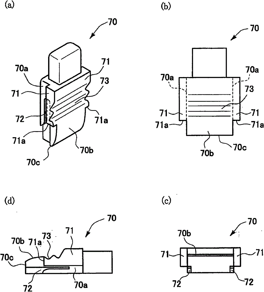
[0056] A first embodiment of the present invention will be described below with reference to the embodiments shown in the drawings. figure 1 is a schematic diagram showing an example of a sectional configuration of a hub unit equipped with the rotation detection unit of the present invention, figure 2 is an exploded perspective view showing an example of a rotation detection unit according to an embodiment of the present invention, image 3 are perspective, plan, front and side views showing an example of a head, Figure 4 is a perspective view, a plan view, a front view and a side view showing an example of a holding portion, Figure 5 is a perspective view showing an example of a state where the head is mounted in the holding portion, and Image 6 yes Figure 5 side view. It should be noted that in figure 1 In , the left-hand side in the figure indicates the vehicle outer side, and the right-hand side in the figure indicates the vehicle inner side.

[0057] Such as f...

no. 2 example

[0075] Next, an embodiment of a rotation detection sensor mounting structure according to a second embodiment of the present invention will be described with reference to the drawings. Figure 7 are perspective and side views showing an example of a head, Figure 8 is a perspective view, a plan view, a front view and a side view showing an example of a holding portion, Figure 9 is a perspective view showing an example of a state where the head is mounted in the holding portion, and Figure 10 yes Figure 9 side view. It should be noted that in the following description, different parts from the embodiments described above will be mainly described, and parts similar to those of the foregoing embodiments are given like reference numerals so that descriptions are omitted or simplified.

[0076] Next, pass Figure 7 with 8 Detailed forms of the head portion 70 and the holding portion 83 in the second embodiment will be described. As in the case of the foregoing embodiments,...

no. 3 example

[0092] Next, an embodiment of a rotation detection sensor mounting structure according to a third embodiment will be described with reference to the drawings. Figure 16 are perspective and side views showing an example of a head, Figure 17 is a perspective view and a side view showing an example of a holding portion, Figure 18 is a perspective view showing an example of a state where the head is mounted in the holding portion, and Figure 19 yes Figure 18 side view.

[0093] As in the case of the foregoing embodiments, the head portion 70 and the holding portion 83 constitute a part of the rotation detection unit 6 for detecting a change in rotation of the drive shaft 2 of the hub unit 1 . The head 70 detects the rotation of the pulsar ring 60 in the hub unit 1, and the holding portion 83 is arranged on the annular cover member 80 to hold the head 70 on the vehicle inner side (refer to figure 1 , 2 ). The head portion 70 is formed of a polymer material such as resin,...


PUM


Abstract

End faces in a push-in direction of swelling portions which swell from both side portions of a head portion are received by flat surfaces formed on receiving portions of a resilient piece. By the distal end faces of the swelling portions being received by the flat surfaces of the receiving portions, the head portion is positioned in a radial direction by a holding portion, whereby a pressing action (a resilient action) of the resilient piece can be applied forwards towards the head portion from a position lying further rearwards than the receiving positions. By this configuration, a radial positioning of the head portion and the prevention of radial dislocation of the head portion are facilitated.

Description

technical field [0001] The present invention relates to a rotation detection sensor installation structure and a hub unit including such a rotation detection unit. Background technique [0002] Generally, a rotation detection unit for detecting a rotation speed of a wheel is mounted on a hub unit of a motor vehicle. The rotation detection unit is used, for example, as an information input device of an anti-lock braking system (ABS) of a motor vehicle. For example, the rotation detection unit has: an impulse ring fixed to the inner ring side of the hub unit; The rotation of the impulsive ring changes as the wheel rotates. [0003] In such a rotation detection sensor mounting structure, there is a structure in which the head of the sensor is radially pushed into a holding portion (sensor holder) formed on the supporting ring member, and the holding portion (sensor holder) formed on the holding The elastic part (clip part) on the part is engaged with the engaging part (locki...

Claims


Application Information

Patent Timeline
Patent Type & Authority Patents(China)
IPC IPC(8): G01P3/487F16C19/18F16C41/00
CPCF16C19/186F16C33/7886F16C33/805F16C41/007F16C2326/02G01P1/00G01P1/026G01P3/443G01P3/487
Inventor 增田善纪石山峻也
Owner JTEKT CORP
Why Eureka
Try Eureka