
Anti-loosening threaded pair comprising limiting faces and anti-loosening threaded parts

A technology of limiting surfaces and threaded parts, which is applied in the direction of threaded fasteners, nuts, bolts, etc., can solve the problems of broken threaded connection structural parts, loose threaded connection failure, and reduced connection force, so as to improve fastness and facilitate The effect of repeated use and moderate tightening torque

Inactive Publication Date: 2018-08-14
BEIJING INSTITUTE OF TECHNOLOGYGY
View PDF8 Cites 1 Cited by
  • Summary
  • Abstract
  • Description
  • Claims
  • Application Information

AI Technical Summary

Problems solved by technology

[0003] However, under complex working conditions (vibration, shock, alternating temperature, etc.), threaded connections are often prone to loosening and failure
Thread looseness will not only reduce the connection force, but also induce the overall fracture of threaded structural parts (such as bolts), causing serious safety accidents

Method used


Image

  • Anti-loosening threaded pair comprising limiting faces and anti-loosening threaded parts
  • Anti-loosening threaded pair comprising limiting faces and anti-loosening threaded parts
  • Anti-loosening threaded pair comprising limiting faces and anti-loosening threaded parts

Examples


Embodiment 1

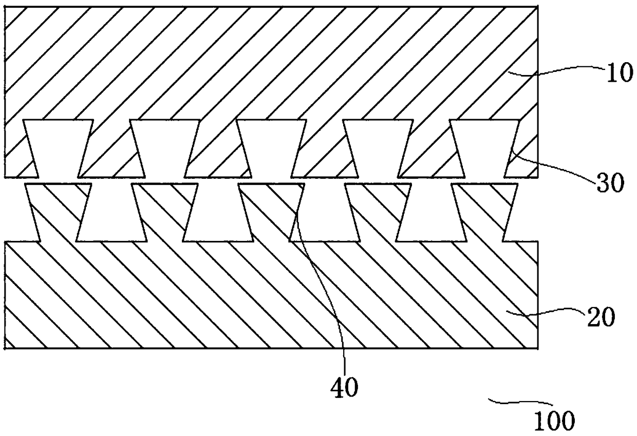
[0085] As shown in FIG. 1( a ) and FIG. 1( b ), the anti-loosening thread pair 100 including the limiting surface is mainly composed of a first threaded part 10 and a second threaded part 20 . An inner hole may be processed on the first screw member 10, and the inner wall of the inner hole may be processed with first thread teeth extending along a helical line. A rod-shaped structure can be processed on the second screw member 20, and the outer wall surface of the rod-shaped structure of the second screw member 20 can be processed with second thread teeth extending along a helical line, and the second thread teeth can correspond to the first thread teeth . In this embodiment 1, the first threaded member 10 is tightened to the left relative to the second threaded member 20, and the left-right direction shown in Figure 1(b) is the load-bearing direction, thereby forming a force-bearing mating surface and a non-bearing Force fit surface.

[0086] The first limiting surface 30 i...

Embodiment 2

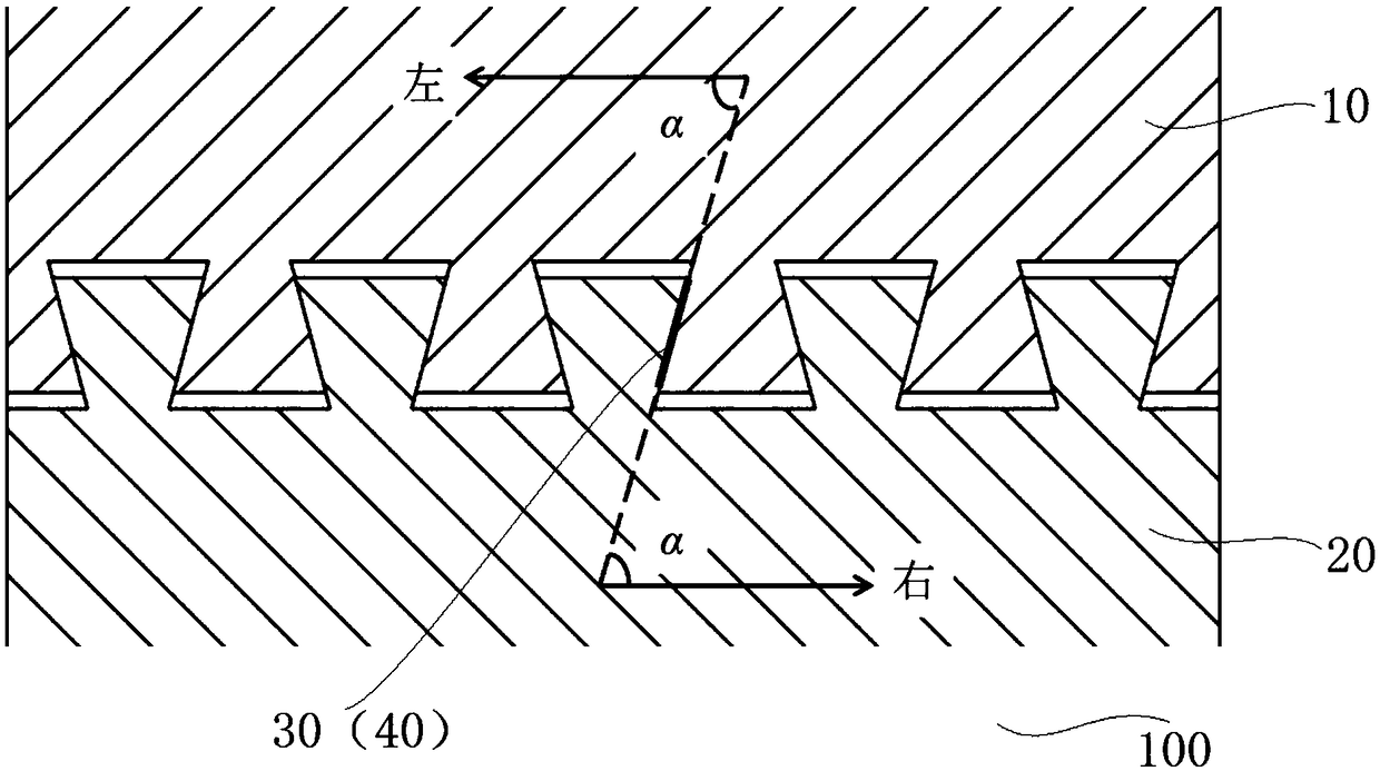
[0088] As shown in Figure 2 (a) and Figure 2 (b), the main structure of the anti-loosening thread pair 100 comprising the limiting surface in the present embodiment 2 is basically the same as the above-mentioned embodiment, in the present embodiment 2, the first A threaded member 10 is screwed leftward relative to the second threaded member 20, and the left-right direction as shown in FIG. 2(b) is the bearing direction, thereby forming a force-bearing mating surface and a non-force-bearing mating surface.

[0089] The first limiting surface 30 is processed as a part of the first force-bearing mating surface of the first threaded part 10, and the second limiting surface 40 is processed as a part of the second force-bearing mating surface of the second threaded part 20, The first limit surface 30 and the second limit surface 40 overlap and form a straight line in the cross-sectional view shown in Figure 2 (b), the extension of the straight line (i.e. the extension of the coincide...

Embodiment 3

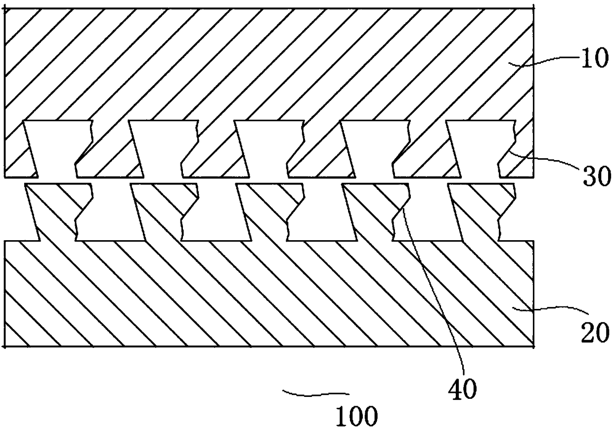
[0091] As shown in Figure 3 (a) and Figure 3 (b), the main structure of the anti-loosening thread pair 100 comprising the limiting surface in the present embodiment 3 is basically the same as the above-mentioned embodiment, in the present embodiment 3, the first A threaded member 10 is tightened to the left relative to the second threaded member 20, and the left and right direction as shown in FIG.

[0092] The first limiting surface 30 is processed as a part of the curved surface on the first force-bearing mating surface of the first threaded part 10 , and the second limiting surface 40 is processed as a part of the second force-bearing mating surface of the second threaded part 20 Curved surface, the first limit surface 30 and the second limit surface 40 overlap and form a curve segment in the cross-sectional view shown in Fig. The angle formed by the bearing directions of the first threaded member 10 and the second threaded member 20 is an acute angle α, which effectively p...


PUM


Abstract

The invention provides an anti-loosening threaded pair comprising limiting faces and anti-loosening threaded parts. The anti-loosening threaded pair comprises the first threaded part and the second threaded part. The first threaded part is provided with a first threaded tooth, and the second threaded part is provided with a second threaded tooth. When the first threaded part faces the screwing direction of the second threaded part, the sides, squeezed by each other, of the first threaded tooth and the second threaded tooth form force-bearing matching faces correspondingly, and the sides, opposite to the force-bearing matching faces, of the first threaded tooth and the second threaded tooth form non-force-bearing matching faces correspondingly. The first force-bearing matching face and / or the first non-force-bearing matching face of the first threaded tooth are each / is provided with the first limiting face. The second force-bearing matching face and / or the second non-force-bearing matching face of the second threaded tooth are each / is provided with the second limiting face. Each first limiting face corresponds to the corresponding second limiting face in a stopping and abutting manner so that radial staggering formed between the first threaded part and the second threaded part can be limited. By means of the anti-loosening threaded pair, radial staggering formed between the first threaded part and the second threaded part can be effectively avoided.

Description

technical field [0001] The invention relates to the technical field of mechanical connection, and more specifically, to an anti-loosening screw pair and an anti-loosening screw including a limiting surface. Background technique [0002] Threaded connection is one of the most widely used connection methods in the fields of machinery, construction, transportation, aviation, aerospace, ships, furniture, etc. It can generate a large connection force, is easy to repeatedly disassemble and assemble, is easy to mass produce, and has low cost. [0003] However, under complex working conditions (vibration, shock, alternating temperature, etc.), threaded connections are often prone to loosening and failure. Thread loosening will not only reduce the connection force, but also induce the overall fracture of threaded structural parts (such as bolts), causing serious safety accidents. Contents of the invention [0004] In view of this, the present invention provides an anti-loosening t...

Claims


Application Information

Patent Timeline
Patent Type & Authority Applications(China)
IPC IPC(8): F16B33/00
CPCF16B33/00
Inventor 巩浩刘少丽丁晓宇刘检华
Owner BEIJING INSTITUTE OF TECHNOLOGYGY
Learn More