System and method for control of an autonomous drive related operation

a technology of autonomous driving and control system, which is applied in the direction of instruments, movable seats, dashboard fitting arrangements, etc., can solve the problems that the actions of the vehicle should not be performed in an un-safe or otherwise unexpected manner, the disengagement of the autonomous driving mode of the vehicle should not be performed in an un-safe or unexpected manner, and the safety of one or more vehicle occupants. to achieve the effect of reducing the risk of accidents

Active Publication Date: 2017-10-10
VOLVO CAR CORP
View PDF9 Cites 1 Cited by
  • Summary
  • Abstract
  • Description
  • Claims
  • Application Information

AI Technical Summary

Benefits of technology

[0007]An object of the present disclosure is to provide a control system and a method for controlling an autonomous drive related operation of a vehicle which seek to mitigate, alleviate, or eliminate one or more of the above-identified deficiencies.

Problems solved by technology

For instance, engaging or disengaging an autonomous driving mode of the vehicle should not be performed in an un-safe or otherwise unexpected manner, since this would jeopardize the safety of the one or more vehicle occupants, as well as of other road-users in the vicinity of the vehicle.
Consequently, any actions by the vehicle should not be performed in an un-safe manner, nor should it be executed when the occupant does not expect it or wish for it.

Method used


Image

  • System and method for control of an autonomous drive related operation
  • System and method for control of an autonomous drive related operation
  • System and method for control of an autonomous drive related operation

Examples


example vehicle

[0068 Operations

[0069]FIG. 8 is a flow diagram depicting example method steps, performed in a vehicle 100, 100′ substantially as described herein, for controlling an autonomous drive related operation of the vehicle 100, 100′. It should be appreciated that FIG. 8 comprises some operations which are illustrated with solid border, and some operations which are illustrated with a dashed border. The operations which are comprised in a solid border are operations which are comprised in the broadest embodiment of the present teaching. The operations which are comprised in a dashed border are example embodiments which may be comprised in, or a part of, or are further operations which may be taken in addition to the operations of the broader example embodiments. It should furthermore be appreciated that the operations need not be performed in order.

example operation 8

[0070]Example Operation 8

[0071]According to some embodiments, the vehicle 100, 100′ is configured to issue 8 an alert signal when a detection of a predetermined foot arrangement does not occur within a pre-determined time duration measured from a time instant when at least one other condition out of the at least two conditions is fulfilled. The control unit 140 discussed above, e.g., in relation to FIG. 1, is configured to issue the alert signal when the detecting does not occur within a pre-determined time duration measured from the time instant when at least one other condition out of the at least two conditions is fulfilled.

[0072]As explained above in relation to at least FIG. 2, and under subheading ‘Controlling vehicle autonomous driving mode state’, the issuing of such an alert is helpful in order to notify the occupant of the reason an autonomous drive related operation fails to commence.

[0073]Operation 10

[0074]The vehicle 100, 100′ is configured to detect 10 a pre-determined...

example operation 12

[0076]Example Operation 12

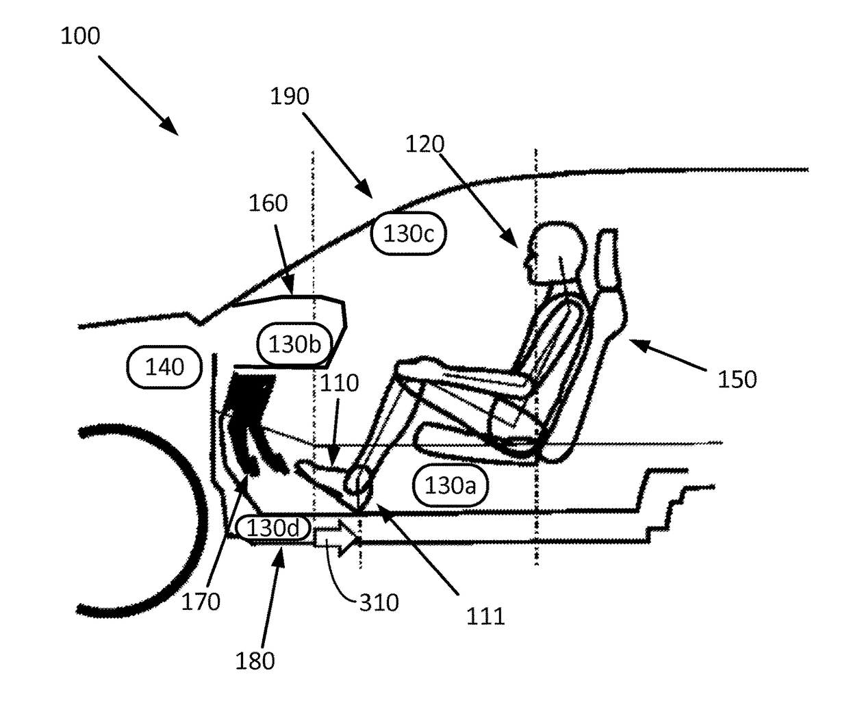
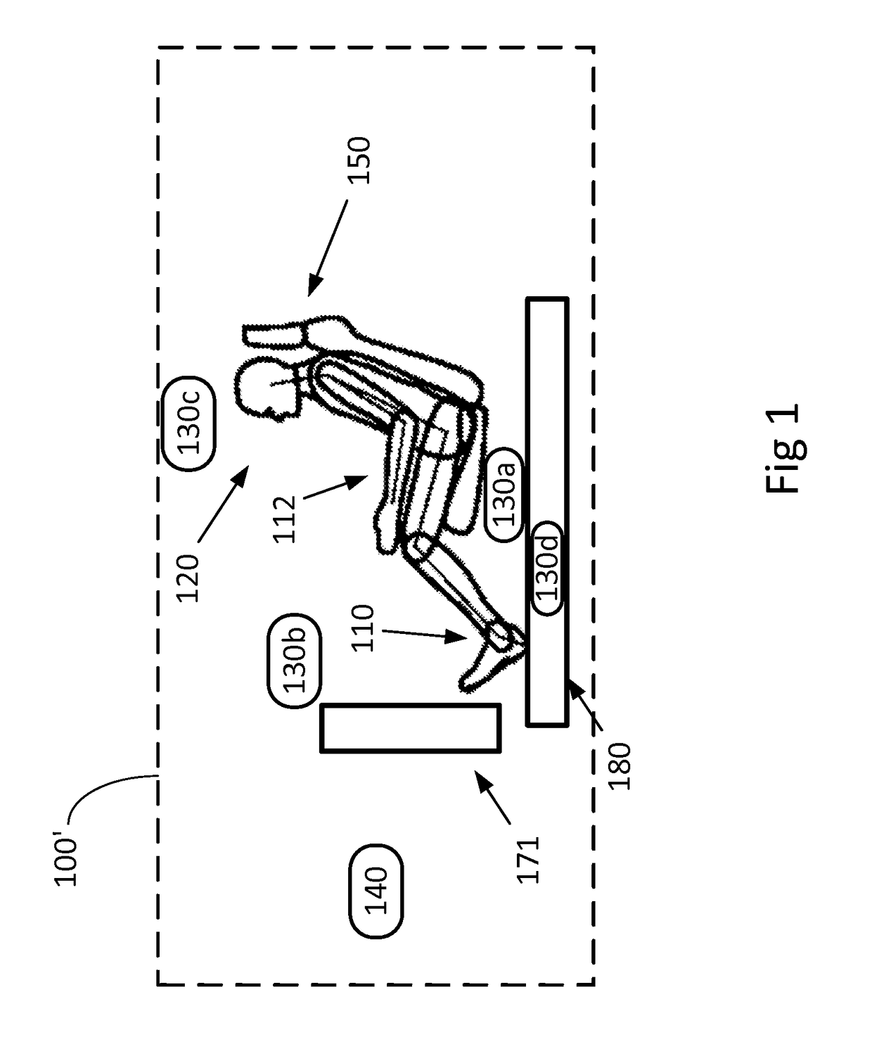
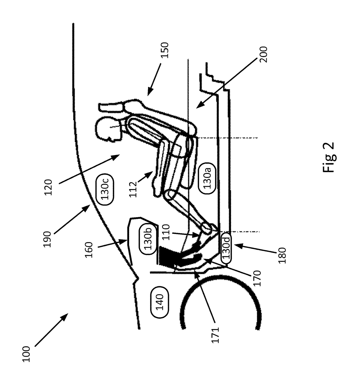
[0077]According to some embodiments, the vehicle 100, 100′ is configured to sense 12 a distance between the feet 110 of the occupant 120 and one or more pedals 170 of the vehicle 100, 100′, and compare the distance to a pre-determined distance threshold. One or more out of the one or more sensors 130a-d comprised in the vehicle 100 and discussed above in connection to at least FIG. 2, and under subheading ‘Vehicle overview’, is arranged to sense the distance between the feet 110 of the occupant 120 and one or more pedals 170 of the vehicle 100, 100′. The control unit 140 is then configured to compare the distance to the pre-determined distance threshold. Having access to information about the distance between the feet and the one or more pedals 170 may be used by the vehicle to secure that the feet cannot get stuck under the pedals of the vehicle upon retracting the front seat, as discussed in connection to FIG. 5a above. Having access to information about ...


PUM


Abstract

A control system and method in a vehicle are disclosed for controlling an autonomous drive related operation of the vehicle. The method may include detecting a pre-determined foot arrangement of an occupant in a front seat of the vehicle and controlling a state of the autonomous drive related operation, based on the detected pre-determined foot arrangement. The system may include at least one sensor configured to detect a pre-determined foot arrangement of an occupant in a front seat of the vehicle, and a control unit configured to control a state of the autonomous drive related operation, based on the detected pre-determined foot arrangement.

Description

CROSS-REFERENCE TO RELATED APPLICATIONS[0001]This application claims foreign priority benefits under 35 U.S.C. 119(a)-(d) to European patent application number EP 14186157.5, filed Sep. 24, 2014, which is incorporated by reference in its entirety.TECHNICAL FIELD[0002]The present disclosure relates to a control system and a method in a vehicle for controlling an autonomous drive related operation of the vehicle.BACKGROUND[0003]Vehicles equipped with control systems for autonomous drive are capable of travelling and interacting with other road-users without direct manual control by one or more occupants in the vehicle. These control systems may be engaged or disengaged depending on whether the occupant in the driving seat wishes to manually control, in example, to drive, the vehicle or if an autonomous driving mode is preferred. Autonomous driving, in general, comprises a plurality of different operations, where each operation is associated with one or more states.[0004]It is of great...

Claims


Application Information

Patent Timeline
Patent Type & Authority Patents(United States)
IPC IPC(8): B60W50/10B60W10/30B60W10/04B60N2/00B60W50/14B60W50/08B60N2/02B60W50/00G06F3/01B60N2/06
CPCB60W50/10B60N2/002B60N2/0244B60W50/0098G06F3/017B60N2/06B60W2050/0095B60K2350/1052B60W30/00B60W2540/00B60K35/00B60K37/06B60K2370/21B60K2370/146
Inventor SUGIOKA, ICHIRO
Owner VOLVO CAR CORP
Why Eureka
Try Eureka