
Method and apparatus for press casting

a press casting and press technology, applied in the field of press casting methods and apparatuses, can solve the problems of increasing the size and complication of the press casting apparatus itself, the apparatus for press casting is unsuitable for relatively small components used for motorcycles, and it is difficult to respond to such requests, so as to reduce production processes, easy to change the design of casting components, and easy to change the design

Active Publication Date: 2014-02-27
HONDA MOTOR CO LTD
View PDF2 Cites 3 Cited by
  • Summary
  • Abstract
  • Description
  • Claims
  • Application Information

AI Technical Summary

Benefits of technology

The present invention provides an apparatus for press casting that allows for easy change in design without changing the entire apparatus. It includes a movable second mold that can change the shape of the casting component, and a fixed mold that forms the mold cavity. The apparatus also includes a communication between the mold cavity and a molten metal passage and a gas exhaust port, which can allow for efficient casting and minimize production processes. Additionally, the apparatus can simultaneously cut off the communication and pressurize the solidification of the molten metal material, reducing the occurrence of sink marks, gas pocket, and misrun. The present invention provides a highly versatile and cost-effective apparatus for press casting.

Problems solved by technology

Accordingly, such apparatus is likely to cause the increase in size and complication of the apparatus for press casting itself.
Moreover, the apparatus for press casting is unsuitable to relatively small components used for motorcycles and the like.
In addition, if it is often requested to change only a part of a mold cavity as in the case of making a plurality of prototypes and the like, it is difficult to respond to such a request with the above-mentioned apparatus for press casting.

Method used


Image

  • Method and apparatus for press casting
  • Method and apparatus for press casting
  • Method and apparatus for press casting

Examples


Embodiment Construction

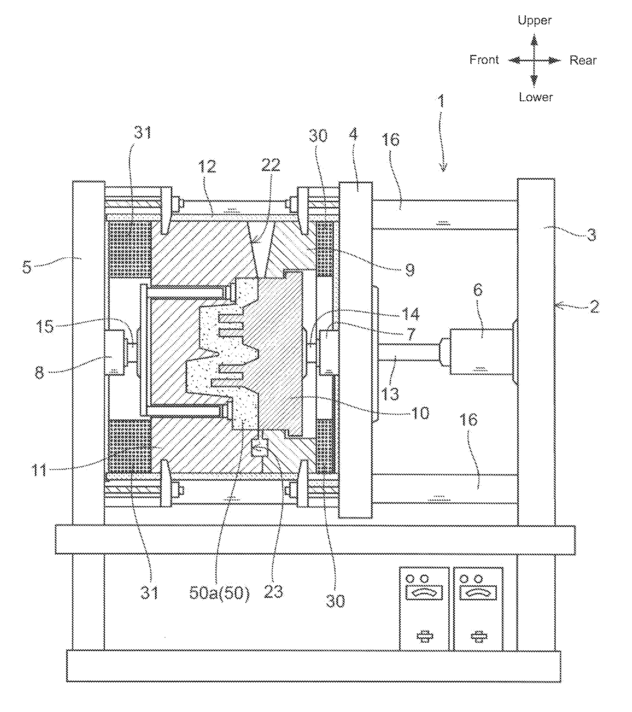
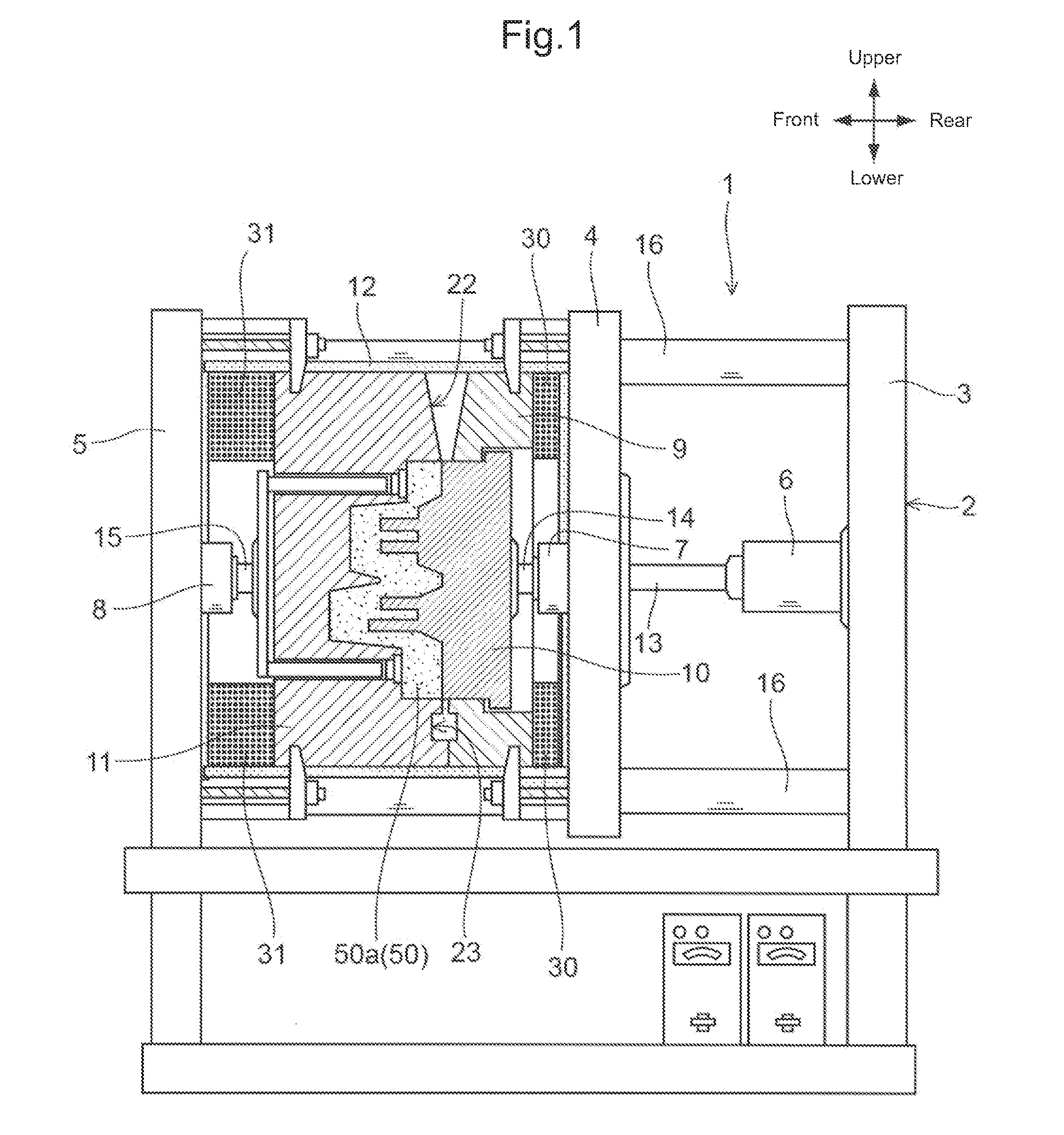
[0036]An illustrative embodiment of the present invention will be described hereinafter in detail with reference to the accompanying drawings. FIG. 1 is a partial left cross-sectional view of an apparatus for press casting 1 according to the embodiment of the present invention. In the following discussion, it is described that the left direction shown in the drawing is the front direction of the apparatus for press casting 1 and the right direction shown in the drawing is the rear direction of the apparatus for press casting 1.

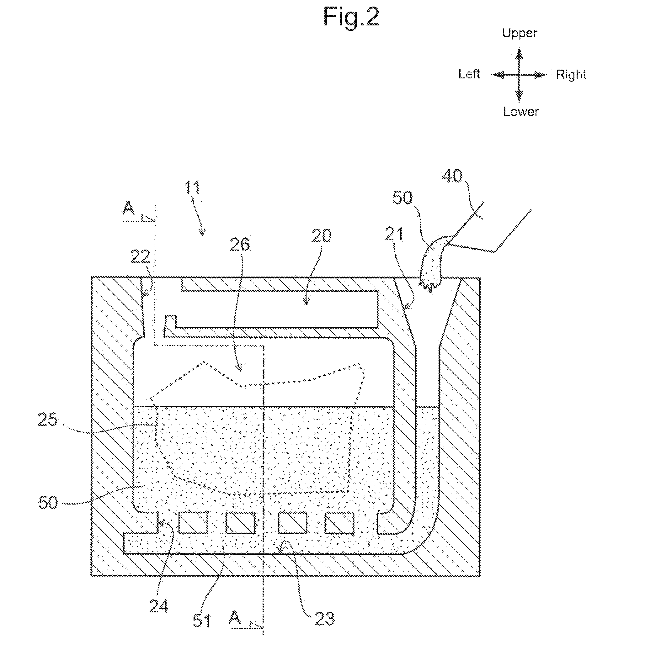
[0037]The apparatus for press casting 1 is an apparatus for producing a cast product 50a by pouring a molten metal material 50 made of molten metal such as aluminum into a mold cavity, which is formed between a fixed mold 11 and a moving mold 9 (also referred to as a first moving mold 9), and by solidifying the molten metal material so as to be pressed. In the present embodiment is characterized in that the mold cavity portion, which forms the shape of the pro...


PUM

PropertyMeasurementUnit
shapeaaaaaaaaaa
sizeaaaaaaaaaa
pressureaaaaaaaaaa

Abstract

An apparatus for press casting includes a casting mold formed of a fixed mold and a first moving mold operable to move relative to the fixed mold. The apparatus further includes a second moving mold operable to move relative to the first moving mold. A mold cavity, which forms a cast product, is configured by the fixed mold and the second moving mold. When the first moving mold is moved to a first predetermined position, a molten metal passage and a gas exhaust port, which communicate with the mold cavity, are formed at positions outside the mold cavity. A communication between the mold cavity and the molten metal passage, and the gas exhaust port is cut off by the second moving mold when the second moving mold is moved to a second predetermined position while the first moving mold is maintained at the first predetermined position thereof.

Description

CROSS-REFERENCE TO RELATED APPLICATIONS[0001]The present invention claims priority under 35 USC 119 based on Japanese patent application No. 2012-186444, filed on Aug. 27, 2012. The entire subject matter of this priority document, including specification claims and drawings thereof, is incorporated by reference herein.BACKGROUND OF THE INVENTION[0002]1. Field of the Invention[0003]The present invention relates to a method and an apparatus for press casting. More particularly, the present invention relates to a method and an apparatus for press casting for solidifying a molten metal material which is poured into a mold cavity so as to be pressed by a moving mold.[0004]2. Description of the Background Art[0005]There is known apparatus for press casting, which constitutes a mold cavity forming the shape of a cast product with a fixed mold and a moving mold, and solidifies a molten metal material poured into the mold cavity so as to be pressed by the moving mold.[0006]An example of an a...

Claims


Application Information

Patent Timeline
Patent Type & Authority Applications(United States)
IPC IPC(8): B22D18/02
CPCB22D18/02B22D27/11B22D17/22B22D18/04
Inventor KITAMURA, TAKUNORIYANAGITA, HIROOMI
Owner HONDA MOTOR CO LTD
Learn More