Lighting system, image display apparatus using the same and light diffusion plate used therefor

a technology of light diffusion plate and image display apparatus, which is applied in the direction of lighting and heating apparatus, identification means, instruments, etc., can solve the problems of reducing the thickness of the body, not always appropriate in view of productivity, and the edge light type cannot provide sufficient luminance, etc., to achieve uniformity and luminance angle distribution, improve productivity of lighting system, and reduce power consumption

Inactive Publication Date: 2007-06-07
KURARAY CO LTD
View PDF8 Cites 7 Cited by
  • Summary
  • Abstract
  • Description
  • Claims
  • Application Information

AI Technical Summary

Benefits of technology

[0026] The object of the present invention is that a direct type lighting system having a plurality of light sources and an image display apparatus using the same characterized in that: the luminance at the exit plane is increased; the efficiency of using light is increased; it is easily adapted to the large-screen because it is not changed the optical design and is not reduced the luminance and the luminance uniformity along with enlarging the screen; the lamp image is eliminated without strictly aligning the light source with the other members; and the distance between the light source and the other members is narrowed and the film configuration is simplified to reduce the thickness: and a light diffusion plate appropriately used as the member for a direct type lighting system having the light source disposed directly under the principal plane thereof and an image display apparatus using the same, and having high luminance uniformity are provided.

Problems solved by technology

Along with the display is enlarged, the edge light type can not provide sufficient luminance because the ratio of the length of the peripheral portion in which the light source can be disposed to the display area is reduced so that it is not supplied with sufficient quantities of light.
However, the luminance increasing film comes expensive and the large number of films is required so that it is not always appropriate in view of productivity and reducing the thickness of the body.
Additionally, the edge light type has another problem that the weight of the optical waveguide is increased along with enlarging the display.
Thus, recently it is difficult for the edge light type to meet the requirements of the marketplace such as the large-screen and high luminance display.
Additionally, the thickness of the display is disadvantage than the edge light system.
Thus, it is further difficult to resolve the problem of the lamp image.
The conventional means used by the edge light type, i.e. the diffusion sheet on which light diffusing particles is applied can not resolve the problem of the lamp image.
However, in the method of using the light diffusing particles, light is absorbed into the light diffusing particles and diffused into the unnecessary direction so that the efficiency of using light is reduced.
Additionally, the lamp image can be reduced by disposing adjacently a number of light sources, meanwhile power consumption is increased undesirably.
Accordingly, the method is not appropriate.
Therefore, the problem that it is nonproductive occurs.
Therefore, the sufficient luminance uniformity can not be obtained.
However, the large number of light diffusing particles to eliminate the lamp image, which significantly reduce the efficiency of using light should be avoided to be used in view of energy saving.

Method used


Image

  • Lighting system, image display apparatus using the same and light diffusion plate used therefor
  • Lighting system, image display apparatus using the same and light diffusion plate used therefor
  • Lighting system, image display apparatus using the same and light diffusion plate used therefor

Examples


embodiment 1

[0157] The lighting system and the image display apparatus provided in the present invention will be described with reference to FIG. 1-FIG. 34 as the embodiment 1.

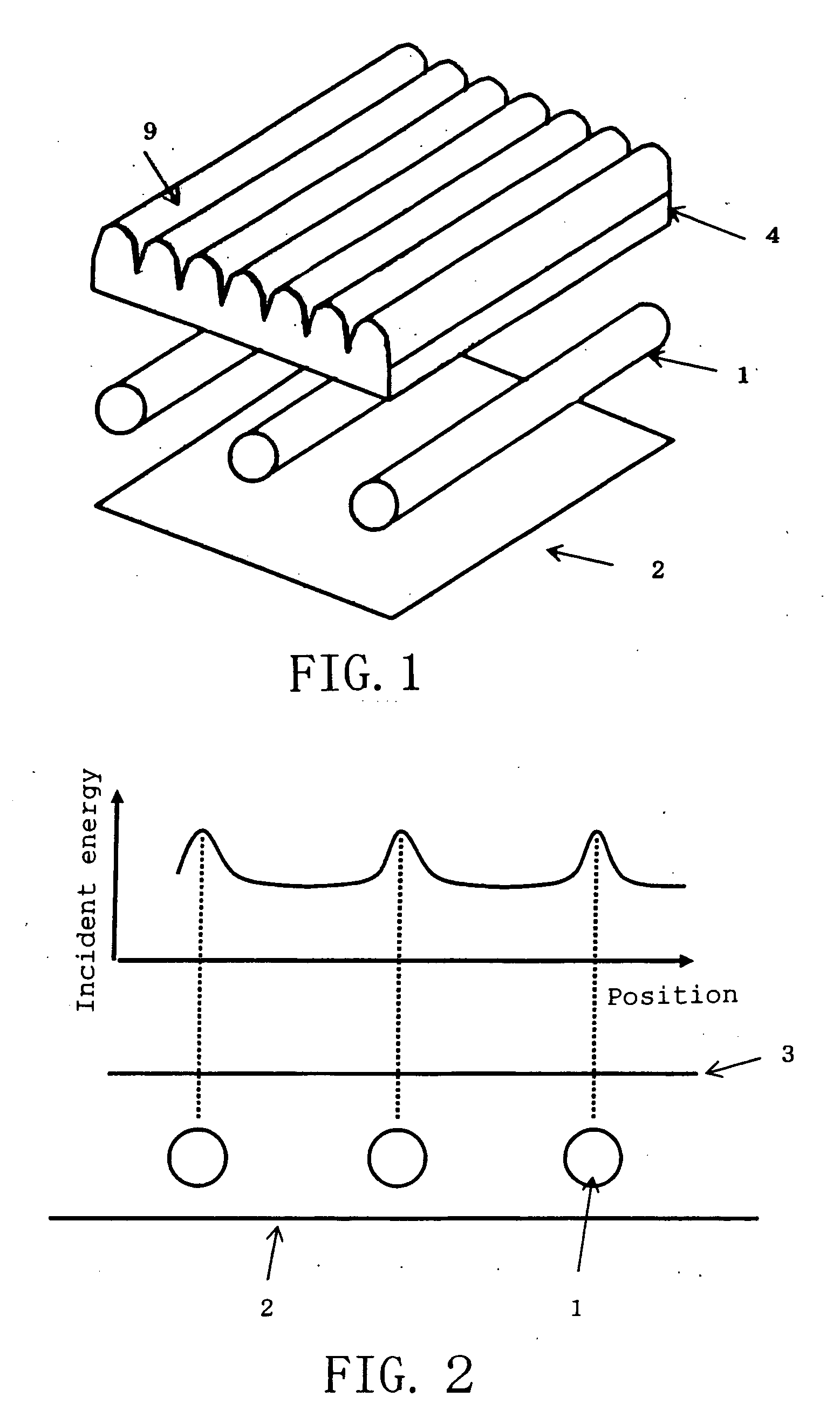
[0158] A reflector 2, a plurality of light sources 1 and a light control member 4 are sequentially disposed from a light incident side to a light outgoing side as FIG. 1. A plurality of convex structure is regularly formed on the light control member 4.

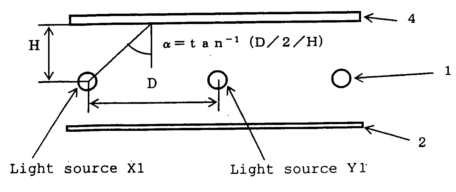
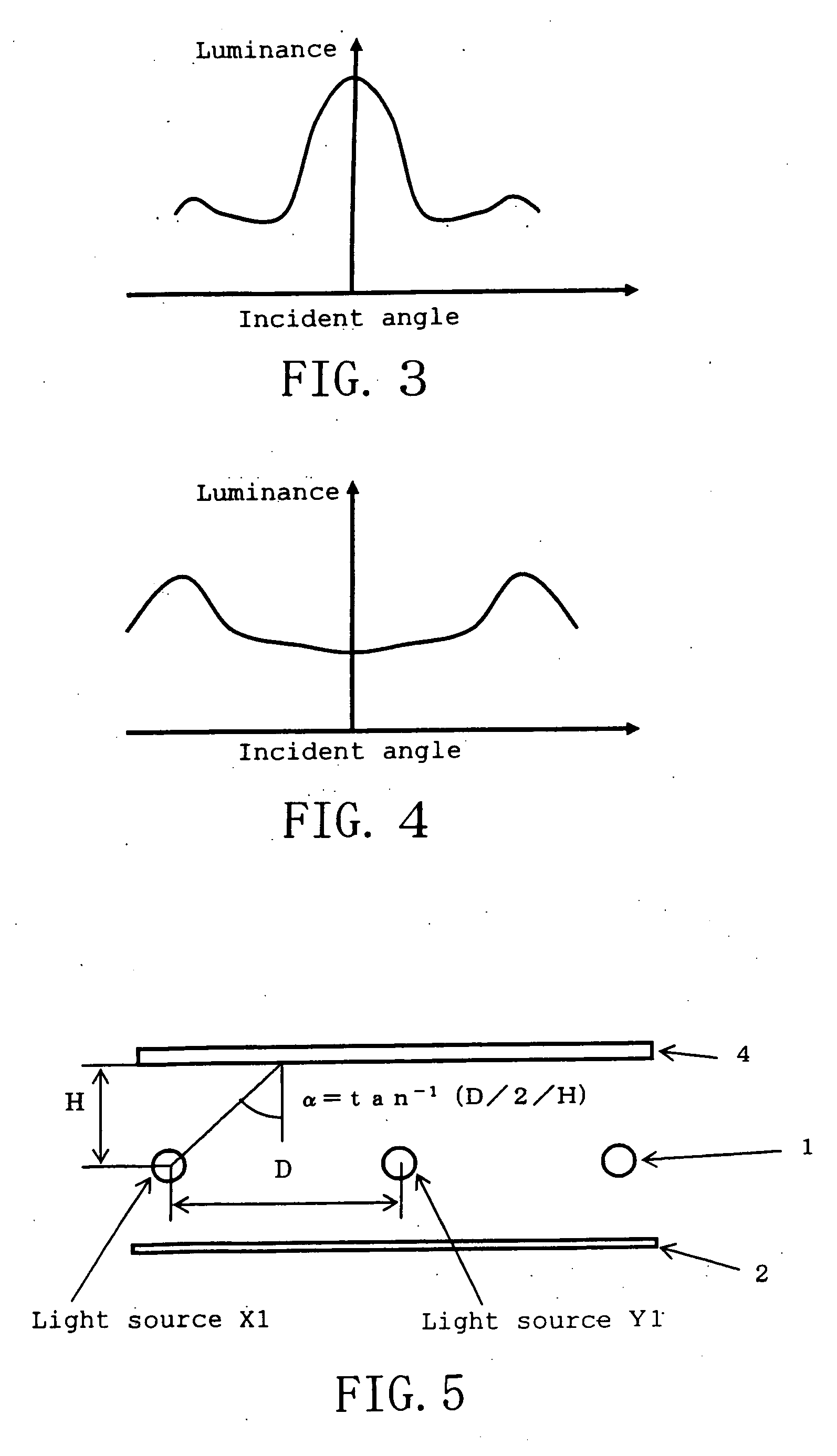
[0159] In the lighting system including the plurality of light sources 1 on the reflector 2, the incident energy of the light incident on a vertical imaginary plane 3 perpendicular to the front direction (upward in the figure) is different between the portion directly above each light source 1 and the portion directly above between each adjacent light source 1 as FIG. 2. The imaginary plane 3 is equivalent to the incident plane of the light control member 4 in FIG. 1 and it is means that the incident energy on the light control member 4 is different between the portion di...

embodiment 2

[0284] The light diffusion plate provided by the present invention will be described with reference to FIG. 39-FIG. 57 as the Embodiment 2.

[0285]FIG. 39a-FIG. 39c represent examples of the lighting system including the light diffusion plate according to the present invention. In FIG. 39a, a light diffusion plate 201 including convex structures 202 on the exit plane side thereof is disposed above the viewing screen side of the light source 204 selected from linear light sources such as cold fluorescent lamps and a point light source such as an incandescent lamp, and a reflector 205 is provided inside the housing to enclose the light source and the light diffusion plate. In FIG. 39b, the light diffusion plate 201 including convex structures 202 and approximately flat portions 218 on the incident plane and convexoconcaves 23 on the exit plane is disposed above the viewing screen side of a plurality of (three in the figure) linear light sources 204 at even intervals and in parallel eac...


PUM

PropertyMeasurementUnit
angleaaaaaaaaaa
angleaaaaaaaaaa
thicknessaaaaaaaaaa

Abstract

The invention is directed to a lighting system having a reflector, light sources and a light control member sequentially disposed from a light incident side to a light outgoing side. Preferably used for large displays requiring high uniformity, this invention eliminates lamp image and removes the necessity to do light source repositioning, while enabling luminance in the exit plane to achieve excellent luminosity and uniformity. This invention achieves total light transmittance of more that 50% when light is incident at a predetermined angle α from the normal direction of the incident plane and achieves 1.05-3 times more total light transmittance than when the light is from a direction normal to the incident plane. This is achieved by the light control member by controlling the ration between total light transmittance in the positions of greater transmittance and the total transmittance in the positions of lesser transmittance.

Description

BACKGROUND OF THE INVENTION [0001] 1) Field of the Invention [0002] The present invention relates to a direct type lighting system, an image display apparatus using the same and a light diffusion plate used therefore. Especially, the present invention relates to a direct type lighting system, an image display apparatus using the same and a light diffusion plate used therefore which are preferably used for large electric signboards and liquid crystal display devices required high luminance and luminance uniformity. [0003] 2) Description of the Related Art [0004] As for example of the lighting system for the image display apparatus, there are two types of lighting systems, one of which is an edge light type that the light from a light source is directed to the front direction by an optical waveguide and uniformly distributed through a diffusion sheet, and the other of which is an direct type that a light source is disposed behind the lighting plane and the light is uniformly distribut...

Claims


Application Information

Patent Timeline
Patent Type & Authority Applications(United States)
IPC IPC(8): F21V7/04F21V5/00F21V5/02G02B5/02G02F1/1335G02F1/13357G09F9/00G09F13/04
CPCG02B5/0278G02B5/0231G02B5/0221G02F1/133611G02F2001/133607G09F13/0409G02F2001/133507G02B5/0215G02F1/133507G02F1/133607F21V11/00G02F1/1335
Inventor ONISHI, IKUOHORIKOSHI, SATOKOITO, TOSHIYUKIKIKUYAMA, SHIGEKI
Owner KURARAY CO LTD
Why Eureka
Try Eureka