Door frame construction, fuselage portion and aircraft or spacecraft

a door frame and fuselage technology, applied in the direction of fuselages, door leaves, transportation and packaging, etc., can solve the problems of disadvantageous heavyness cracks of this type, and high requirements in particular on the fatigue limit of door frame formers, and achieve the effect of high weigh

Inactive Publication Date: 2014-02-27
AIRBUS OPERATIONS GMBH
View PDF19 Cites 2 Cited by
  • Summary
  • Abstract
  • Description
  • Claims
  • Application Information

AI Technical Summary

Benefits of technology

[0006]One idea of the present invention is to provide an approac

Problems solved by technology

The fact that the door opening weakens the fuselage portion in this region means that there are high requirements in particular on the fatigue limit of the door frame formers.
Cr

Method used


Image

  • Door frame construction, fuselage portion and aircraft or spacecraft
  • Door frame construction, fuselage portion and aircraft or spacecraft
  • Door frame construction, fuselage portion and aircraft or spacecraft

Examples


Embodiment Construction

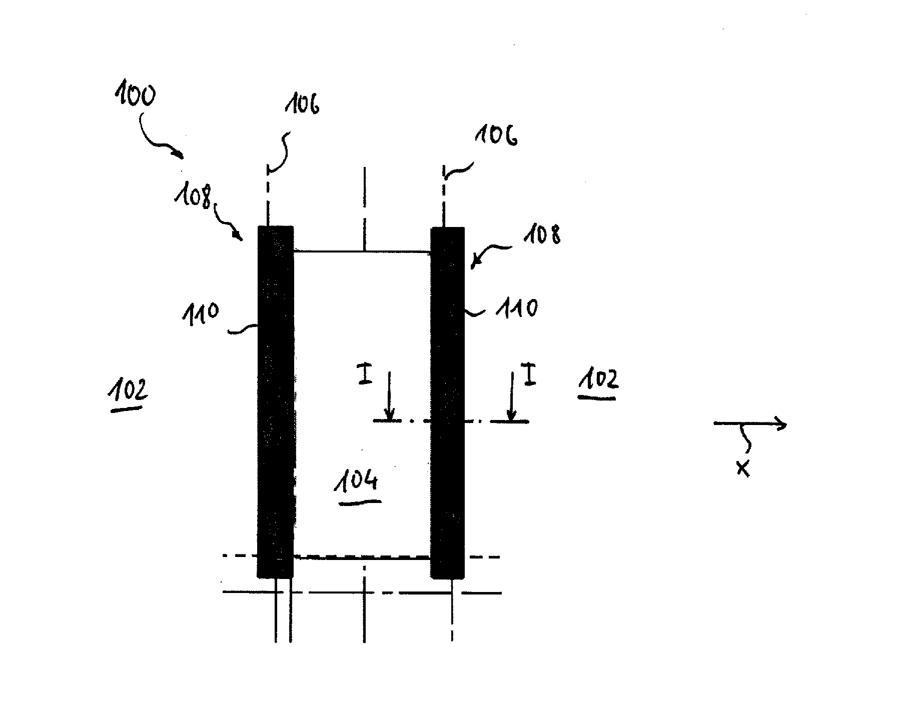
[0028]FIG. 1 is a side view of a fuselage portion 100 according to an embodiment of the present invention.

[0029]The fuselage portion 100 is a component of an aircraft (not further shown).

[0030]The fuselage portion 100 comprises an outer skin 102 which is formed having a door opening 104. In each case, together with two formers 106, which are indicated here only by a line, the outer skin 102 forms a door frame construction 108. The formers 106 are arranged in succession in the longitudinal direction X of the aircraft.

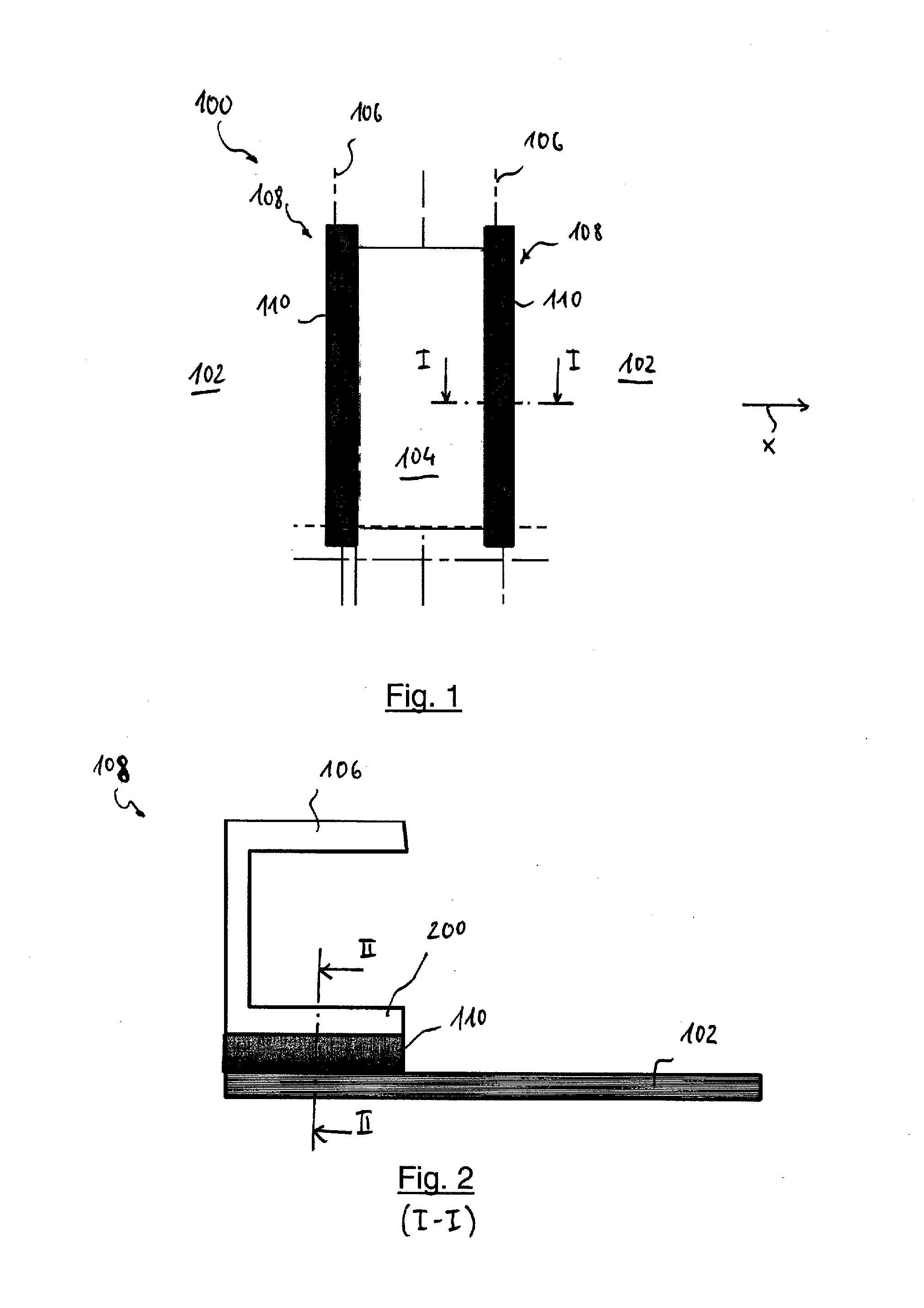
[0031]The construction of a respective door frame construction 108 will be described in greater detail in the following with reference to FIG. 2, which is a sectional view along line I-I from FIG. 1.

[0032]The door frame construction 101 comprises, in addition to the former 106 and the outer skin 102, a glass fibre metal laminate 110, which is arranged between the outer skin 102 and the former 106, in particular an outer flange 200 thereof. The glass fibre metal laminate ...


PUM


Abstract

The present invention provides a door frame construction in particular for an aircraft or spacecraft, including a former; a fibre metal laminate which is connected to the former; and an outer skin which is connected to the fibre metal laminate.

Description

CROSS-REFERENCES TO RELATED APPLICATIONS[0001]This application is a continuation of and claims priority to PCT / EP2012 / 053022 filed Feb. 22, 2012 which claims the benefit of and priority to U.S. Provisional Application No. 61 / 447,169, filed Feb. 28, 2011, and German patent application No. 10 2011 004 844, filed Feb. 28, 2011, the entire disclosures of which are herein incorporated by reference.FIELD OF THE INVENTION[0002]The present invention relates to a door frame construction, to a fuselage portion and to an aircraft or spacecraft.BACKGROUND OF THE INVENTION[0003]Fuselage portions for aircraft are usually produced using a so-called lightweight construction from an outer skin which is reinforced on the inside thereof by a two-dimensional structure consisting of stringers extending in the longitudinal direction of the aircraft and formers extending in the transverse direction of the aircraft.[0004]Furthermore, it is known to provide fuselage portions of this type with door openings ...

Claims


Application Information

Patent Timeline
IPC IPC(8): B64C1/14E06B3/70B64C1/06
CPCB64C1/1461E06B3/7015B64C1/1407B64C1/06
Inventor PLOKKER, MATTHIJSPELLENKOFT, FREDERIK
Owner AIRBUS OPERATIONS GMBH
Why Eureka
Try Eureka