Camera For Photogrammetry And Aerial Photographic Device

a technology of aerial photography and camera, which is applied in the field of camera for photogrammetry and aerial photographic device, can solve the problems of difficult to accurately measure the position of the camera for photogrammetry, and the photogrammetry is constantly changing, and achieves the effects of accurate acquisition, convenient operation and accurate acquisition

Active Publication Date: 2014-02-27
KK TOPCON
View PDF4 Cites 44 Cited by
  • Summary
  • Abstract
  • Description
  • Claims
  • Application Information

AI Technical Summary

Benefits of technology

[0022]Further, according to the present invention, in the camera for photogrammetry, GPS positional information is acquired at a predetermined time interval by the GPS device, the video camera acquires frame images at a predetermined time interval as video images, the control device performs image matching sequentially of still image acquired by the still image camera and the frame image, detects a frame image matching the still image, and judges GPS positional information corresponding to the moment of acquisition of the frame image detected as a position where the still image has been acquired. As a result, even when there is a time lag between the time when shutter signal is issued to the still image camera and the moment of acquisition of still images, positional information at the time of image acquisition can be acquired accurately.
[0023]Also, according to the present invention, in the camera for photogrammetry, a clock signal generating unit, wherein acquisition of GPS position information by the GPS device is synchronized with acquisition of the frame image via a clock signal issued by the clock signal generating unit, and based on the detected frame image, acquisition time and GPS positional information acquired before and after the acquisition time, positional information of the moment of acquisition of the detected frame image is obtained by interpolation. As a result, even when there is a lag in terms of time between the time of acquisition of the detected frame image and the time of acquisition of the GPS positional information, positional information at the time of image acquisition can be acquired accurately.
[0024]Further, according to the present invention, in the camera for photogrammetry, the other device is a flying vehicle. As a result, acquiring images by which aerial photogrammetry can be easily carried out is possible.
[0025]Also, according to the present invention, the camera for photogrammetry further comprises a tilt sensor for detecting an angle between an optical axis of the photographing device main unit and vertical line, wherein the control device corrects image pickup position at the moment of image pickup based on detection result of the tilt sensor. As a result, even when the photographic device main unit is tilted with respect to the vertical line, accurate image pickup position can be obtained.
[0026]Further, according to the present invention, an aerial photographic device comprising a flying vehicle and a camera for photogrammetry, wherein the flying vehicle has a main frame arranged at the central portion, and a predetermined number of propeller units installed via propeller frame on the main frame, and wherein the camera for photogrammetry is installed on the main frame so that said camera for photogrammetry passes through the center of the main frame in up-to-bottom direction, and the optical axis of the camera for photogrammetry is set so as to direct in vertical direction by gravitational force applied on the camera for photogrammetry. Thus, it is possible to acquire the image by which for aerial photogrammetry can be performed in easier manner.
[0027]Furthermore, according to the present invention, the photographic device main unit has a magnetic compass, a gyro unit, a flight control unit for controlling the propeller unit based on signals from the magnetic compass and the gyro unit, and the flying vehicle is arranged so that autonomous flight can be performed. As a result, it is possible to acquire the image, by which aerial photogrammetry can be performed in easier manner within the range as desired.

Problems solved by technology

Therefore, relative positional relation between GPS and the camera for photogrammetry is also constantly changing, and it was difficult to accurately measure the position of the camera for photogrammetry at the time when aerial photograph is taken.

Method used


Image

  • Camera For Photogrammetry And Aerial Photographic Device
  • Camera For Photogrammetry And Aerial Photographic Device
  • Camera For Photogrammetry And Aerial Photographic Device

Examples


Embodiment Construction

[0034]Description will be given below on an embodiment of the invention by referring to the attached drawings.

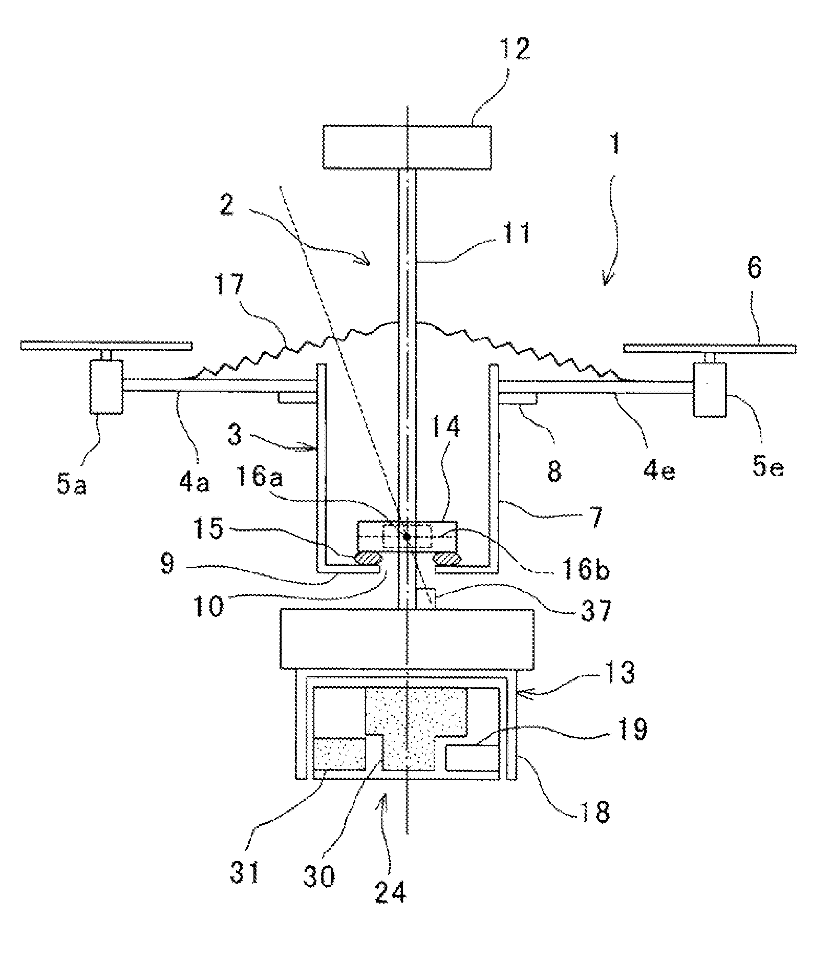
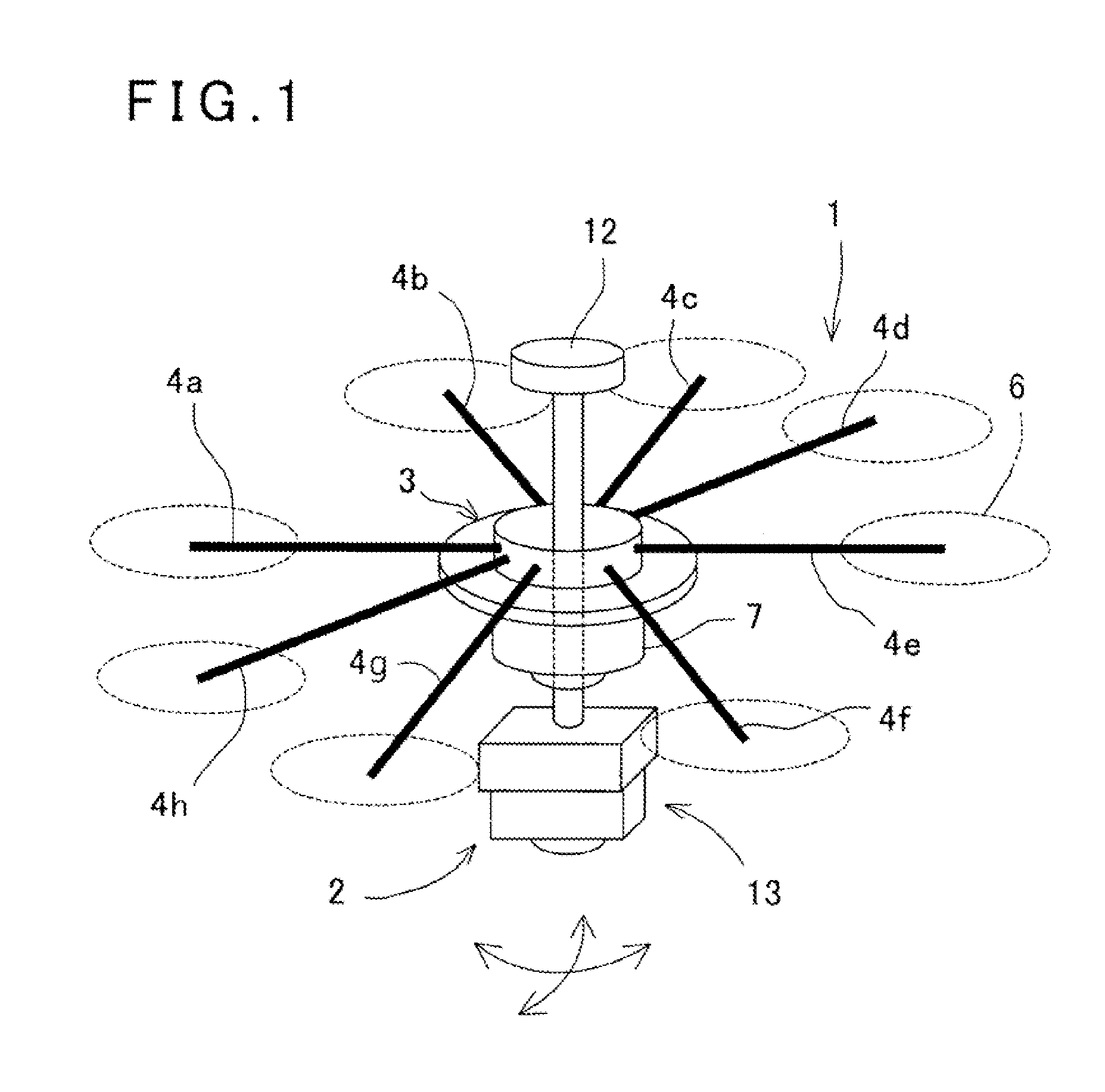
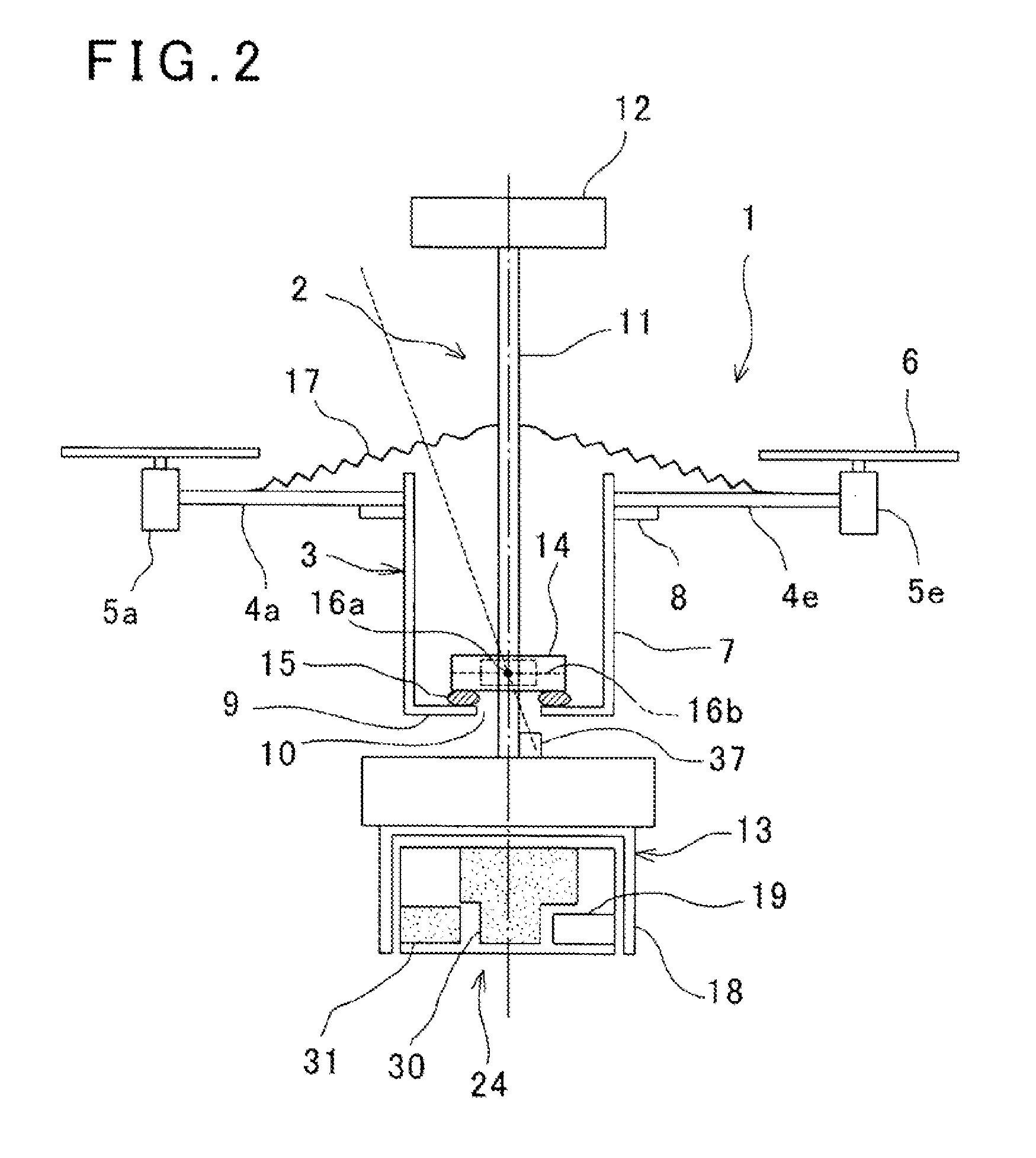
[0035]FIG. 1 and FIG. 2 each represents an aerial photographic device on which a camera for photogrammetry is installed.

[0036]In each of FIG. 1 and FIG. 2, reference numeral 1 represents a flying vehicle, and numeral 2 represents a camera for photogrammetry installed on board of the flying vehicle 1.

[0037]First, description will be given on the flying vehicle 1.

[0038]The flying vehicle 1 has a vehicle body 3. The vehicle body 3 has a plurality and even number of propeller frames 4 to be extended in radial direction, and a propeller unit is installed on a forward end of each the propeller frame 4. The propeller unit has a propeller motor 5 installed at the forward end of the propeller frame 4 and a propeller 6 mounted on an output shaft of the propeller motor 5. The propeller 6 is rotated by the propeller motor 5 and so the flying vehicle 1 flies.

[0039]The vehicle body 3 has ...


PUM


Abstract

The invention provides a camera for photogrammetry, which comprises a shaft 11 tiltably supported in any direction via a gimbal 14, a GPS device having a GPS antenna 12 installed on an upper end of said shaft, and a photographic device main unit 13 installed on a lower end of said shaft, wherein optical axis of said photographic device main unit is designed so as to direct in vertical and downward direction, said photographic device main unit has an image pickup unit 24 installed in a known relation with said GPS antenna and a control device for controlling image pickup of said image pickup unit, and said control device 19 controls said image pickup unit so that still image is acquired by the image pickup unit, and an image pickup position at the time of image pickup is obtained by said GPS device.

Description

BACKGROUND OF THE INVENTION[0001]The present invention relates to a camera for photogrammetry to be installed on a small flying vehicle and an aerial photographic device provided with the camera for photogrammetry.[0002]In recent years, with the progress of UAV (Unmanned Air Vehicle), a camera for photogrammetry is installed on UAV and there has been developed a technique of photogrammetry using the UAV.[0003]Normally, an UAV makes flight by tilting the vehicle body in forwarding direction, while tilting of the vehicle body of the UAV is very likely to be influenced by the speed of propulsion and by wind, and stability of the tilting is low. On the other hand, in aerial photogrammetry, it is necessary to highly precisely photograph the images in vertical and downward direction, and the stability of the tilting of the camera is required.[0004]For this reason, normally, in aerial photographing, a gimbal, which is driven and controlled, is mounted on a vehicle body of the UAV, and aeri...

Claims


Application Information

Patent Timeline
Patent Type & Authority Applications(United States)
IPC IPC(8): H04N7/18
CPCH04N7/18G01C11/06G01C11/02H04N23/66H04N23/80H04N23/667B64U2101/30
Inventor OHTOMO, FUMIOOTANI, HITOSHIOSARAGI, KAZUKIYAMADA, MITSUHARU
Owner KK TOPCON
Why Eureka
Try Eureka