Surface expanding spacer

a spacer and surface technology, applied in the field of surface expanding spacers, can solve the problems of minimizing the safety margin and presenting a notable challenge, and achieve the effect of preventing the expulsion of grafts

Active Publication Date: 2014-02-27
DEPUY SYNTHES PROD INC
View PDF1 Cites 7 Cited by
  • Summary
  • Abstract
  • Description
  • Claims
  • Application Information

AI Technical Summary

Benefits of technology

[0024]Graft material can be injected around and through the fingers via windows in the fingers. Alternatively, and uniquely to this invention, graft can be injected into the disc space prior to cage insertion and the fingers' narrow distal profile allows for facile penetration into the graft by the cage. Annular fibers of the disk prevent graft expulsion.

Problems solved by technology

Although the use of intervertebral spacers is widespread in spine surgery, they present a notable challenge.
However, this tradeoff may not only predispose the cage to subsidence, it also leads to spacers that are very wide in relation to the available surgical access trajectories, thereby minimizing the margin of safety during their approach.

Method used


Image

  • Surface expanding spacer
  • Surface expanding spacer
  • Surface expanding spacer

Examples


Embodiment Construction

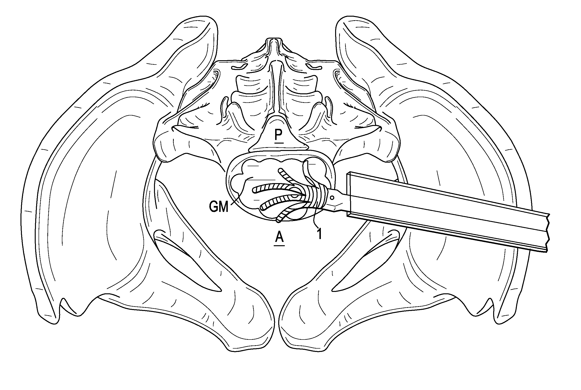
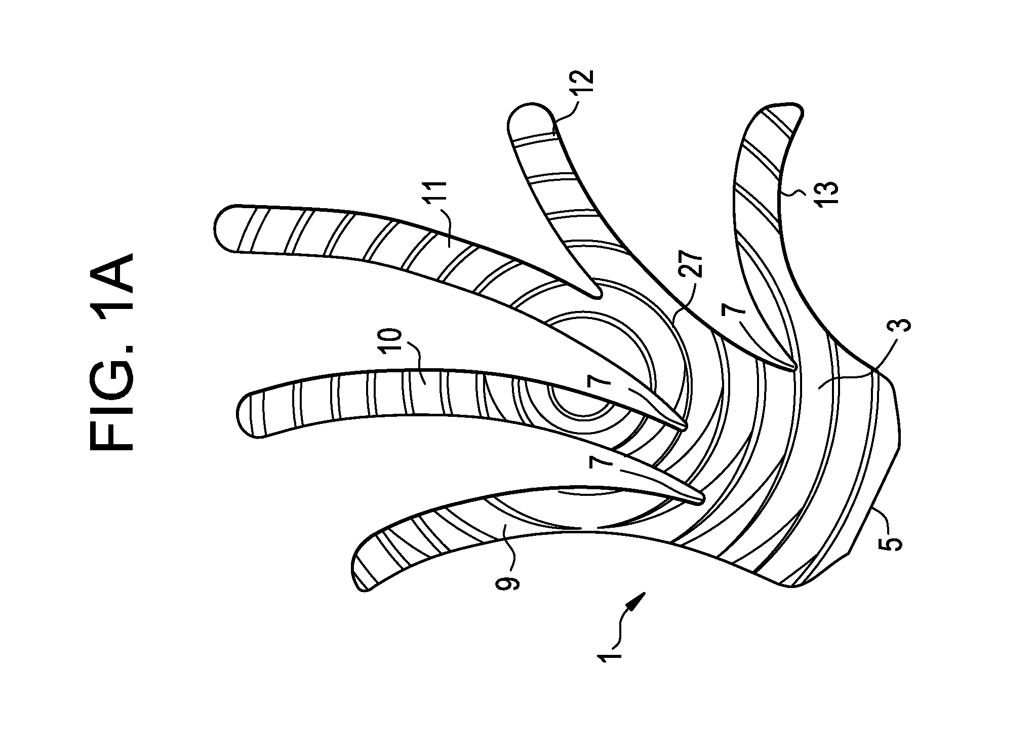
[0041]For the purposes of the present invention, the wall components of the spacer may also be referred to as “fingers”. For the purposes of the present invention, an area between adjoining fingers may be referred to as “web space” or “WS”.

[0042]Now referring to FIG. 1A, there is provided a unitary intervertebral fusion cage 1 comprising:[0043]a) a base 3 having a proximal surface 5 and a distal surface 7, and[0044]b) first, second, third, fourth and fifth elastically deformable fingers 9,10, 11,12, 13 extending distally from the base in a plane.

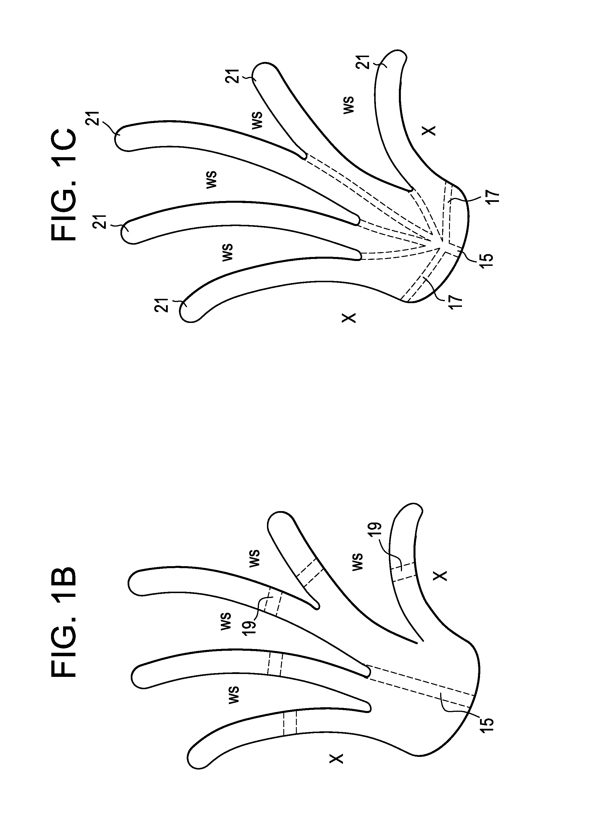
[0045]As shown in FIG. 1B, the cage may further comprise a throughhole 15 beginning on a proximal surface of the base and opening on a distal surface of the base. This throughhole allows cement to be injected into a web space WS of the cage from the proximal base of the cage.

[0046]Also as shown in FIG. 1B, the cage may further have at least one finger comprising a substantially transverse throughhole 19. This type of throughhole allows cemen...


PUM


Abstract

An interbody spacer comprising a series of stacked walls connected by a common base, wherein the spacer collapses when pressed into an access delivery tube. During insertion, the walls can flex as a unit, like bending a deck of cards, to traverse bends in the access tube. Upon distally exiting the portal of the access delivery tube, the walls track apart (like spreading fingers) to create a wide base of support for the vertebral body endplate. A graft delivery device that uses a conveyor belt-type approach to deliver bone graft from the device to a location in a patient. In some embodiments, the conveyor-belt is manually actuated.

Description

CONTINUING INFORMATION[0001]This patent application claims priority from co-pending U.S. Provisional patent application U.S. Ser. No. 61 / 692,326, filed Aug. 23, 2012, entitled “Surface Expanding Spacer”, (Hawkins et al.) (Docket No. DEP6615USPSP), the specification of which is incorporated by reference in its entirety.BACKGROUND OF THE INVENTION[0002]Although the use of intervertebral spacers is widespread in spine surgery, they present a notable challenge. On the one hand, maximizing the amount of surface area of the spacer would appear to better distribute their loads prevailed upon the adjacent vertebral body endplates. On the other hand, maximizing the amount of space preserved for blood and bone graft material would appear to improve the quality and rate of biologic bone growth for fusion and healing. Currently, a tradeoff has been realized in conventional spacers through minimizing the wall thickness of cages to allow for inserted or packed graft or bone growth factor material...

Claims


Application Information

Patent Timeline
Patent Type & Authority Applications(United States)
IPC IPC(8): A61F2/44
CPCA61F2/4455A61F2/4601A61F2/4611A61F2/4644A61F2002/30523A61F2002/30571A61F2002/30579A61F2002/30594A61F2002/30772A61F2002/4627A61F2002/4629A61F2002/4645
Inventor HAWKINS, JOHN RILEYPAVENTO, NICHOLASRAMSAY, CHRISTOPHERSELOVER, SEANLEE, KEVIN
Owner DEPUY SYNTHES PROD INC
Why Eureka
Try Eureka