Cutting Insert and Indexable Rotary Cutting Tool

Inactive Publication Date: 2013-05-23
TUNGALOY CORP
View PDF5 Cites 12 Cited by
  • Summary
  • Abstract
  • Description
  • Claims
  • Application Information

AI Technical Summary

Benefits of technology

[0009]In the case of the square-shaped cutting insert 71, although the number of usable cutting edges is four, an area on plan view is larger than that of the triangular cutting insert 72. That is, since an area not involved in cutting is small in the triangular cutting insert 72, an area of a back support region 74 of the tool body can be taken large, but in the square-shaped cutting insert 71, since an area not involved in cutting is larg

Problems solved by technology

When the holding capability of the cutting insert lowers, chattering or positional shifting of the cutting insert can eas

Method used


Image

  • Cutting Insert and Indexable Rotary Cutting Tool
  • Cutting Insert and Indexable Rotary Cutting Tool
  • Cutting Insert and Indexable Rotary Cutting Tool

Examples


first embodiment

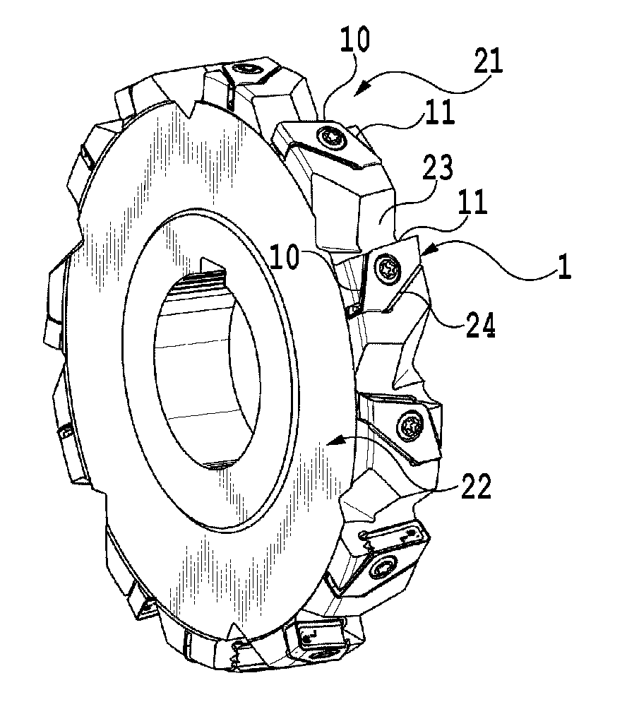
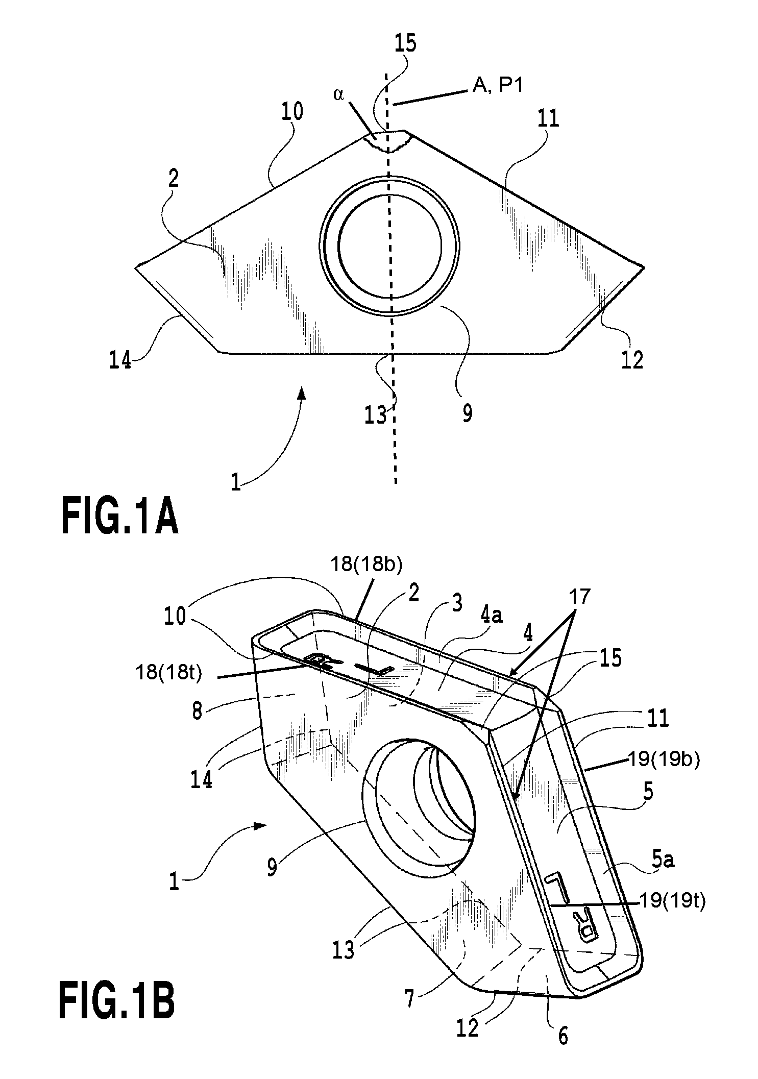
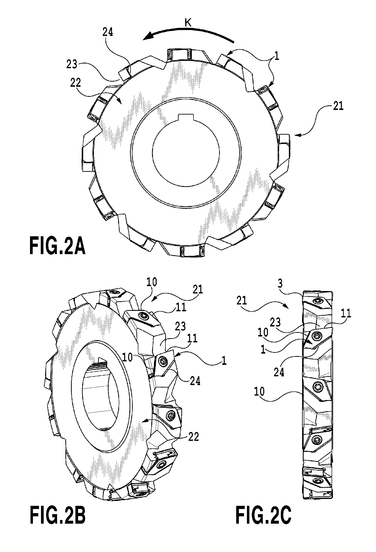
[0078]As illustrated in FIG. 1, a cutting insert 1 according to a first embodiment defines an upper face 2 and a lower face 3, each having a polygonal outer shape, a plurality of side faces 4, 5, 6, 7, and 8 extending between the upper face 2 and the lower face 3, and a mounting hole 9 penetrating from the upper face 2 to the lower face 3. The upper face 2 and the lower face 3 have the same shape and face in opposite directions so as to be substantially parallel to each other. Side faces 4 and 5 can be considered as first and second cutting side faces 4, 5, respectively. Side face 7 can be considered as a central side face 7. Side faces 6 and 8 can be considered as second and first lateral side faces 6, 8, respectively.

[0079]The upper face 2 has, as illustrated in FIG. 1A, a bilaterally symmetric outer shape on top view. The lower face 3 also has the bilaterally symmetric outer shape. Here, in the upper face 2, there are five intersection portions 10, 11, 12, 13, and 14 intersecting...

second embodiment

[0094]Subsequently, a second embodiment of the present invention will be described by referring to FIG. 3. In a cutting insert 31 of the second embodiment, explanation of the portions having the configuration similar to that of the cutting insert 1 in the first embodiment will be omitted.

[0095]As illustrated in FIG. 3, the second embodiment is configured such that, in addition to the first intersection portion 10 and the second intersection portion 11 on the upper and lower faces, the fifth intersection portion 13 in each of the upper face 2 and the lower face 3 is used as a cutting edge. As a result, the cutting edge of this embodiment has two cutting edges 19t, 18b for left hand, two cutting edges 18t, 19b for right hand, and two cutting edges 29t, 29b at the center, that is, six cutting edges in total. The fifth intersection portion 13 which is the cutting edge 29t, 29b may be subjected to honing. On the central side face 7 in contact with the fifth intersection portion 13 on the...

third embodiment

[0103]Next, a cutting insert 51 of a third embodiment will be described by referring to FIG. 5. In the cutting insert of the embodiment, explanation of the portions having the same configuration as that of the cutting insert in the first embodiment will be omitted.

[0104]As illustrated in FIG. 5, the embodiment is configured such that a first side-face intersection portion 52 between the first cutting side face 4 and the first lateral side face 8 and a second side-face intersection portion 53 between the second cutting side face 5 and the second lateral side face 6 are used as cutting edges 33a, 33b. A cutting edge is not formed on portions other than these side-face intersection portions 52 and 53. On the cutting side faces 4 and 5, the rake faces 4b and 5b are formed. These rake faces 4b and 5b are formed so as to gradually incline toward the inside of the cutting insert 51 from the side-face intersection portion. On the cutting side faces 4 and 5 on which the rake faces 4b and 5b ...


PUM

PropertyMeasurementUnit
Angleaaaaaaaaaa
Angleaaaaaaaaaa
Shapeaaaaaaaaaa

Abstract

A cutting insert is arranged in a tangential direction on an outer peripheral portion of a tool body, the cutting insert having a reduced area in a top view thereof. The cutting insert has an upper face, a lower face and at least five side faces extending between the upper and lower faces. The upper face of the cutting insert has at least five intersection portions intersecting with the at least five side faces. The at least five intersection portions include first and second intersection portions and third and fourth intersection portions shorter than the first and second intersection portions, respectively. A cutting edge is formed at each of the first and second intersection portions. A rake face is formed on cutting side faces corresponding to the first and second intersection portions, respectively, while a cutting edge flank is formed on the upper face.

Description

CROSS-REFERENCE TO RELATED APPLICATIONS[0001]This is a continuation-in-part of PCT application No. PCT / JP2012 / 059856, filed Apr. 11, 2012, which claims the benefit of Japanese Patent Application 2011-097343, filed Apr. 25, 2011. The contents of the aforementioned applications are hereby incorporated by reference in their entirety.BACKGROUND OF THE INVENTION[0002]1. Field of the Invention[0003]The present invention relates to a cutting insert and an indexable rotary cutting tool to which the cutting insert is attached. More specifically, the present invention relates to a cutting insert used for slot machining and an indexable rotary cutting tool for slot machining.[0004]2. Description of the Related Art[0005]As one of rotary cutting tools capable of slot machining, an indexable side cutter is known. In a plate-like cutting insert to be attached to the indexable side cutter, there are known a type in which either of upper and lower faces is used as a rake face and is arranged on an o...

Claims


Application Information

Patent Timeline
IPC IPC(8): B23C5/20B23C5/08
CPCB23C5/08B23C5/207B23C2200/0416B23C2200/0444B23C2200/367Y10T407/235B23C5/205B23C5/2213Y10T407/23Y10T407/1942B23C2210/66B23C5/202
Inventor BHAGATH, KEDAR SURESH
Owner TUNGALOY CORP
Why Eureka
Try Eureka