Variable Frequency Helmholtz Resonator

Active Publication Date: 2014-03-06
MANNHUMMEL FILTER SHANGHAI
View PDF13 Cites 3 Cited by
  • Summary
  • Abstract
  • Description
  • Claims
  • Application Information

AI Technical Summary

Benefits of technology

[0004]The object of the present utility model is to overcome the above drawbacks of the prior art by providing a va

Problems solved by technology

Since current Helmholtz resonant cavities are only effective for certain frequencies, they are only effective at certain engine speed of rotation.
To solve this problem, it is sometimes necessary to place a plurality of Helmholtz resonant cavities as branches to the main pipe of an automobile intake system, which leads to problems in cost and instal

Method used


Image

  • Variable Frequency Helmholtz Resonator
  • Variable Frequency Helmholtz Resonator
  • Variable Frequency Helmholtz Resonator

Examples


Example

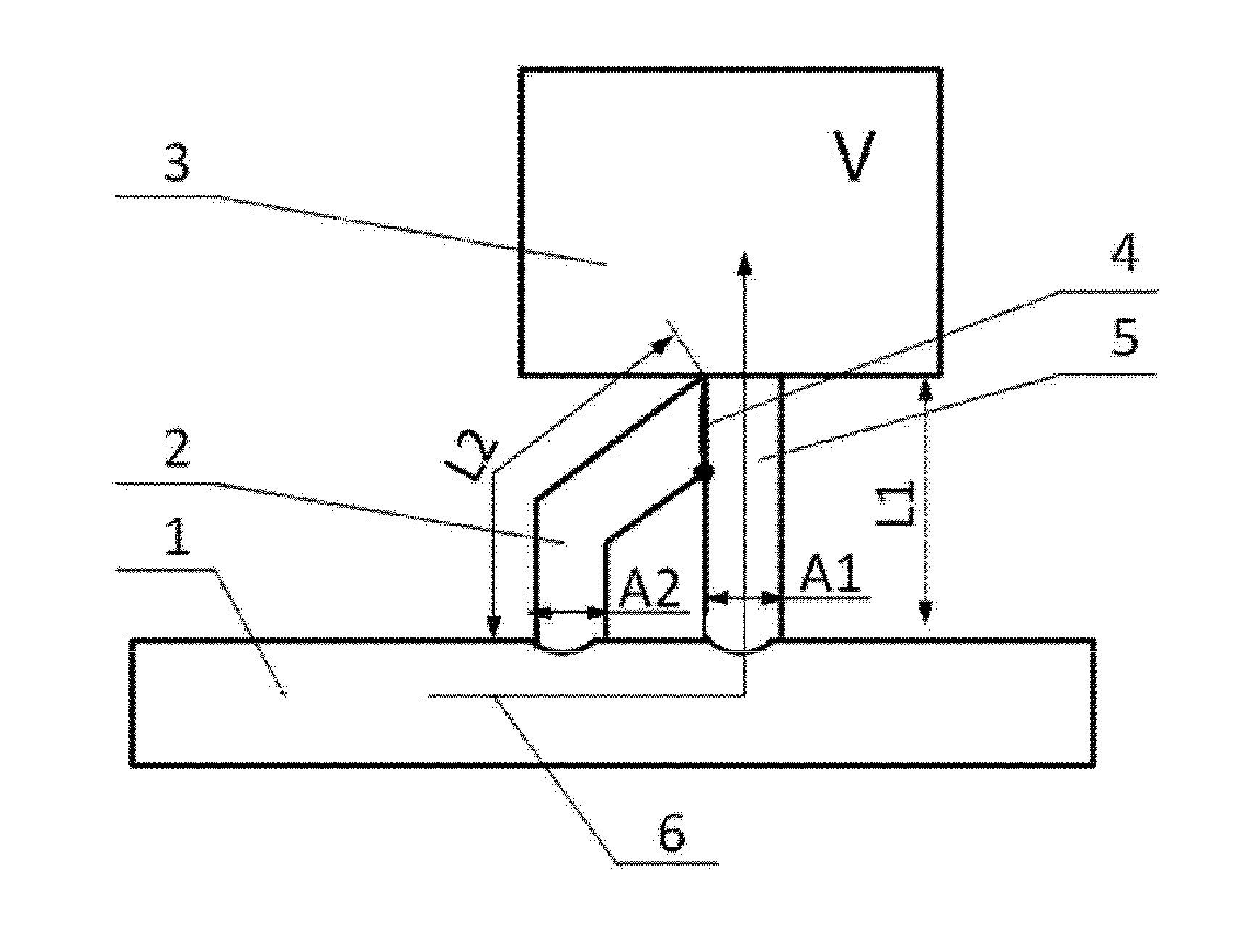
[0015]Wherein the numbers in FIG. 1 represent:

[0016]1. Main pipe of the automobile intake system, 2. Second Helmholtz resonant cavity pipe, 3. Helmholtz resonant cavity body, 4. First control valve plate position, 5. First Helmholtz resonant cavity pipe, 6. First air channel

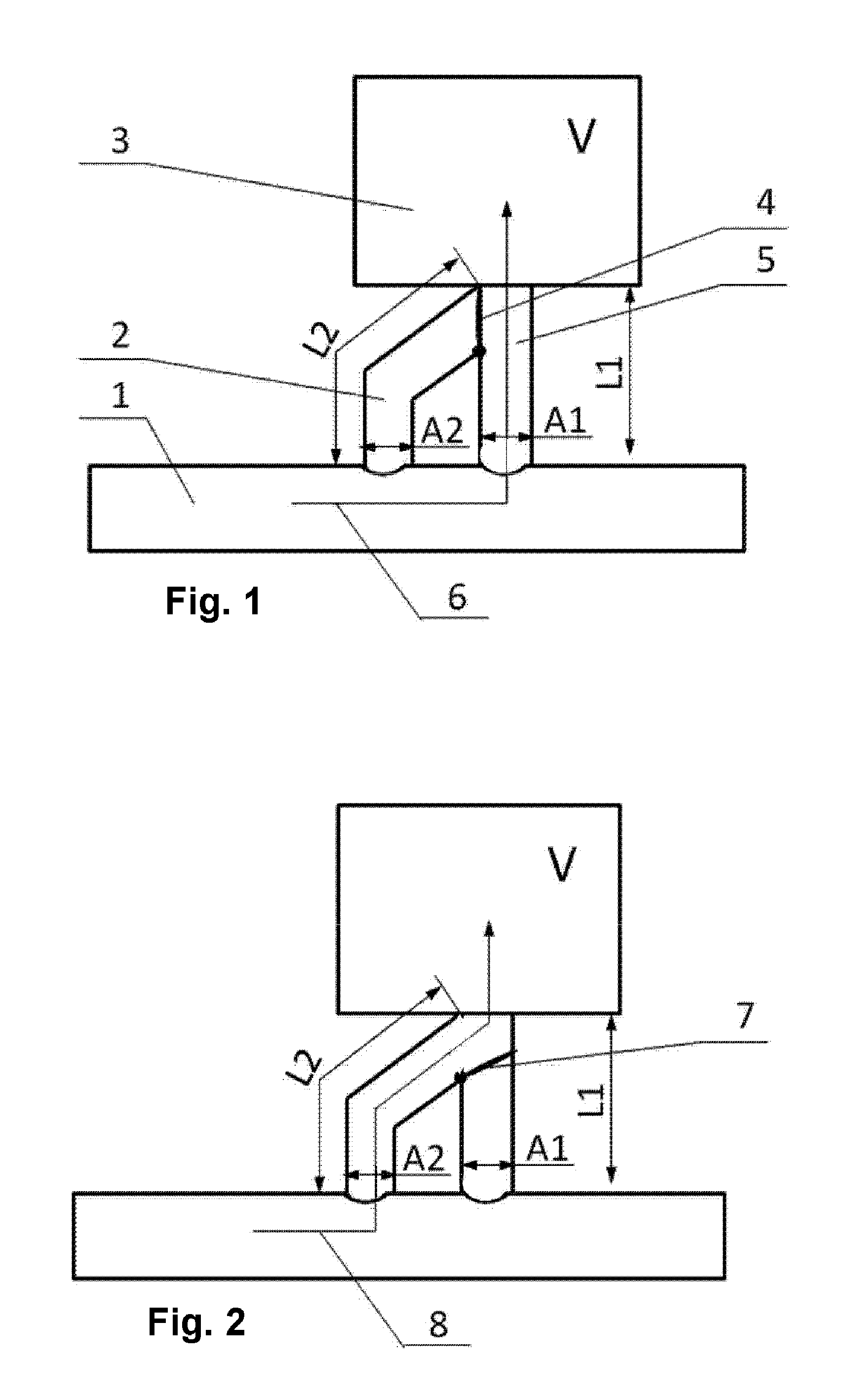
[0017]The numbers in FIG. 2 represent:

[0018]7. Second control valve plate position, 8. Second air channel

DETAILED DESCRIPTION OF THE PREFERRED EMBODIMENT

[0019]The present utility model will be described in detail below with reference to the accompanying drawings and embodiments.

Embodiments

[0020]The present utility model comprises a first Helmholtz resonant cavity pipe 5, a second Helmholtz resonant cavity pipe 2, a control valve plate, and a Helmholtz resonant cavity body 3, and the Helmholtz resonant cavity pipe 5 and the second Helmholtz resonant cavity pipe 2 are connected with the main pipe of the automobile intake system 1, respectively. There is a control valve plate at the location where the Helmholtz reso...


PUM


Abstract

A variable frequency Helmholtz resonant cavity includes a Helmholtz resonant cavity body, two Helmholtz resonant cavity pipes with different cross-sectional areas and lengths and a control valve plate. The Helmholtz resonant cavity body is connected with the main pipe of the intake system via the Helmholtz resonant cavity pipes, and the control valve plate is disposed at the location where the two Helmholtz resonant cavity pipes meet.

Description

FIELD OF THE UTILITY MODEL[0001]The present utility model relates to a Helmholtz resonant cavity, in particular to a variable frequency Helmholtz resonant cavity.DESCRIPTION OF THE RELATED ART[0002]Helmholtz resonant cavity is an effective method to eliminate low frequency components of noises in automobile intake systems. A Helmholtz resonant cavity branched on the main pipe of an automobile intake system can reduce the low frequency noise with certain frequencies in the automobile intake system.[0003]The frequency of low frequency noise components of an automobile intake system is not constant, which would increase along with the increase of engine speed of rotation. Since current Helmholtz resonant cavities are only effective for certain frequencies, they are only effective at certain engine speed of rotation. To solve this problem, it is sometimes necessary to place a plurality of Helmholtz resonant cavities as branches to the main pipe of an automobile intake system, which lead...

Claims


Application Information

Patent Timeline
IPC IPC(8): F01N1/02
CPCF01N1/023F02M35/1222F02M35/1261
Inventor CHEN, QUIANG
Owner MANNHUMMEL FILTER SHANGHAI
Why Eureka
Try Eureka