Injection molding device comprising a slide

Inactive Publication Date: 2014-03-06
VALEO VISION SA
View PDF1 Cites 4 Cited by
  • Summary
  • Abstract
  • Description
  • Claims
  • Application Information

AI Technical Summary

Benefits of technology

[0013]It is an object of the invention to propose a device for molding a thin plastic component com

Problems solved by technology

However, for aesthetic reasons, motor vehicle headlamp shades cannot have an injection mark on their visible faces.
This constraint sometimes makes it difficult to optimize the position of the points at which plastic is injected into the molding cavity, particularly when the molding device comprises a slide.
The problem is that access to an optimum point of injec

Method used


Image

  • Injection molding device comprising a slide
  • Injection molding device comprising a slide
  • Injection molding device comprising a slide

Examples


Example

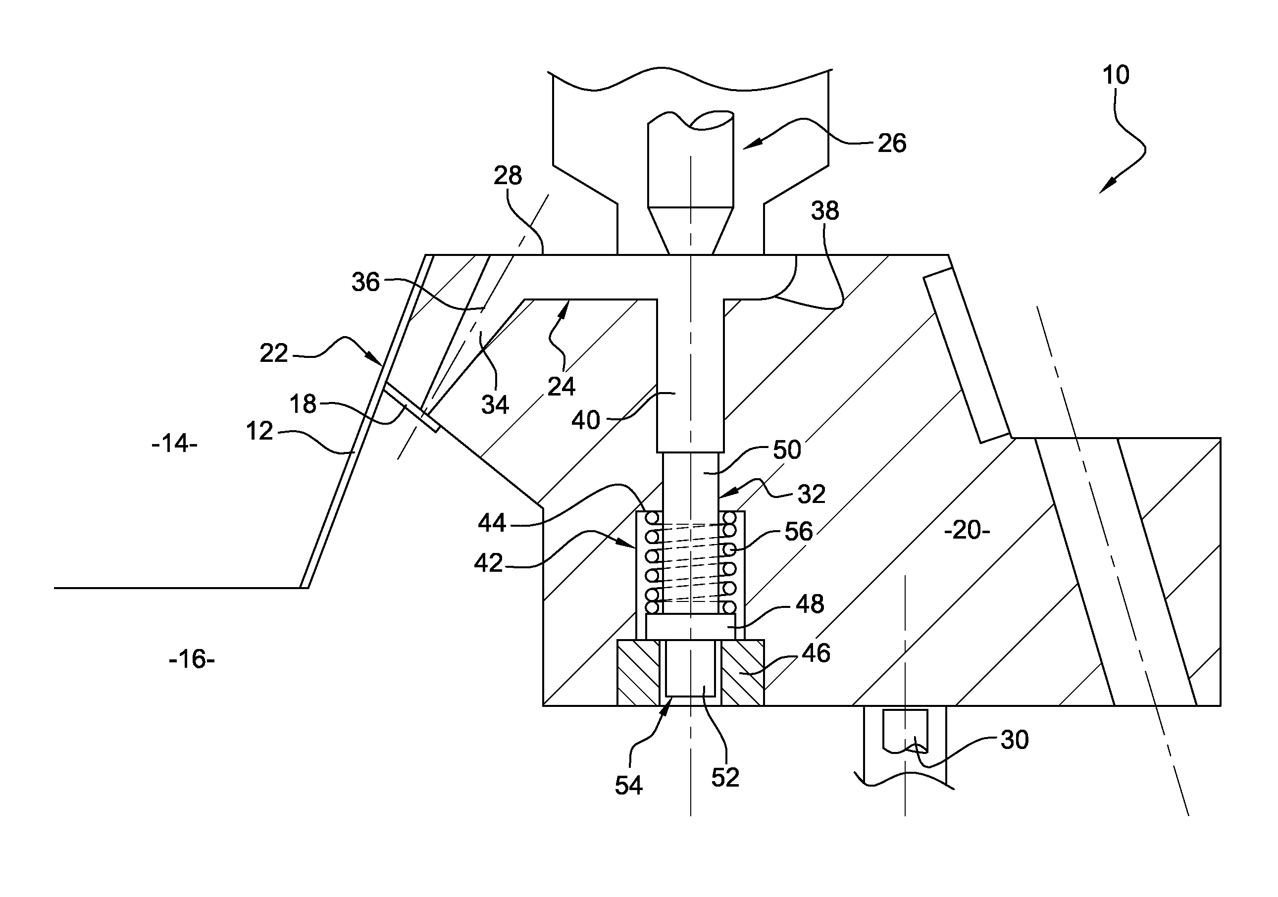
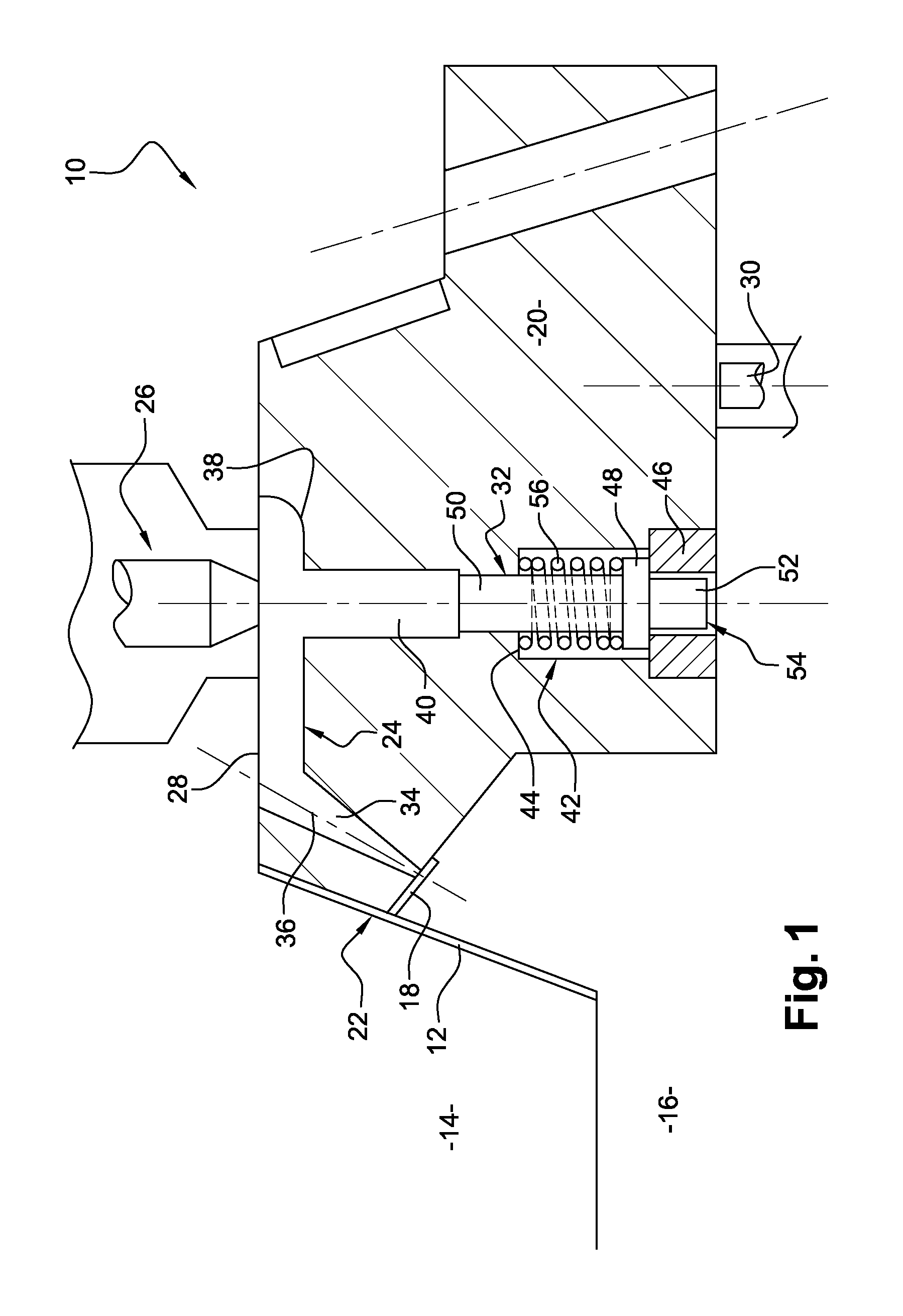
[0039]FIG. 1 depicts a device 10 for injection molding a plastic component 12, such as a motor vehicle headlamp shade.

[0040]The molding device 10 respectively comprises a fixed part 14 and a mobile part 16 which can be moved relative to one another between a position in which the molding device 10 is open and a position in which the device is closed.

[0041]It may be seen from FIG. 1 that the plastic component 12 comprises a rib 18 which has a backdraft surface. In order to be able to release the plastic component 12 after injection molding, the molding device 10 also comprises a slide 20 movable in a translational movement between a position in which the slide is open and a position in which the slide is closed.

[0042]InFIG. 1, the slide 20 and the fixed part 14 and mobile part 16 are in the closed position and form the cavity 22 in which the plastic component 12 is molded.

[0043]The slide 20 comprises a cold runner 24 which opens into that region of the molding cavity 22 that is inten...


PUM

PropertyMeasurementUnit
Fractionaaaaaaaaaa
Shapeaaaaaaaaaa
Plasticityaaaaaaaaaa

Abstract

A device and method for molding a plastic component, comprising a slide movable in a translational movement between a position in which the slide is open and a position in which the slide is closed, the slide comprising a cold runner opening into the molding cavity and the device comprising an ejection member for ejecting plastic sprue formed in the cold runner. The ejection member comprises at least two parts, the first part being borne by the mobile part and the second part being borne by the slide, the slide being movable between a position in which the two parts of the ejection member are offset and a position in which the two parts of the ejection member are more or less aligned so that they can collaborate with one another. The molding cavity comprises a region intended to form a rib or a tab of the plastic component, the cold runner opening into this region.

Description

CROSS-REFERENCE TO RELATED APPLICATIONS[0001]This application claims priority to French Application No. 1258029 filed Aug. 28, 2012, which is incorporated herein by reference and made a part hereof.BACKGROUND OF THE INVENTION[0002]1. Field of the Invention[0003]The present invention relates to the field of the injection-molding of a plastic component, notably a shade for a motor vehicle lighting device.[0004]2. Description of the Related Art[0005]Devices for injection-molding thin plastic components, for example motor vehicle headlamp shades, are known from the prior art. These molding devices usually comprise two parts, respectively a fixed part and a mobile part, which can be moved relative to one another between a position in which the molding device is open and a position in which the device is closed, a slide movable in a translational movement between a position in which the slide is open and a position in which the slide is closed, the two parts and the slide forming a cavity...

Claims


Application Information

Patent Timeline
IPC IPC(8): B29C45/40B29C45/00
CPCB29C45/00B29C45/4005B29C45/1759B29C45/27B29C45/2735B29C45/33B29C45/401B29C45/44
Inventor BOURGAUT, PATRICE
Owner VALEO VISION SA
Why Eureka
Try Eureka